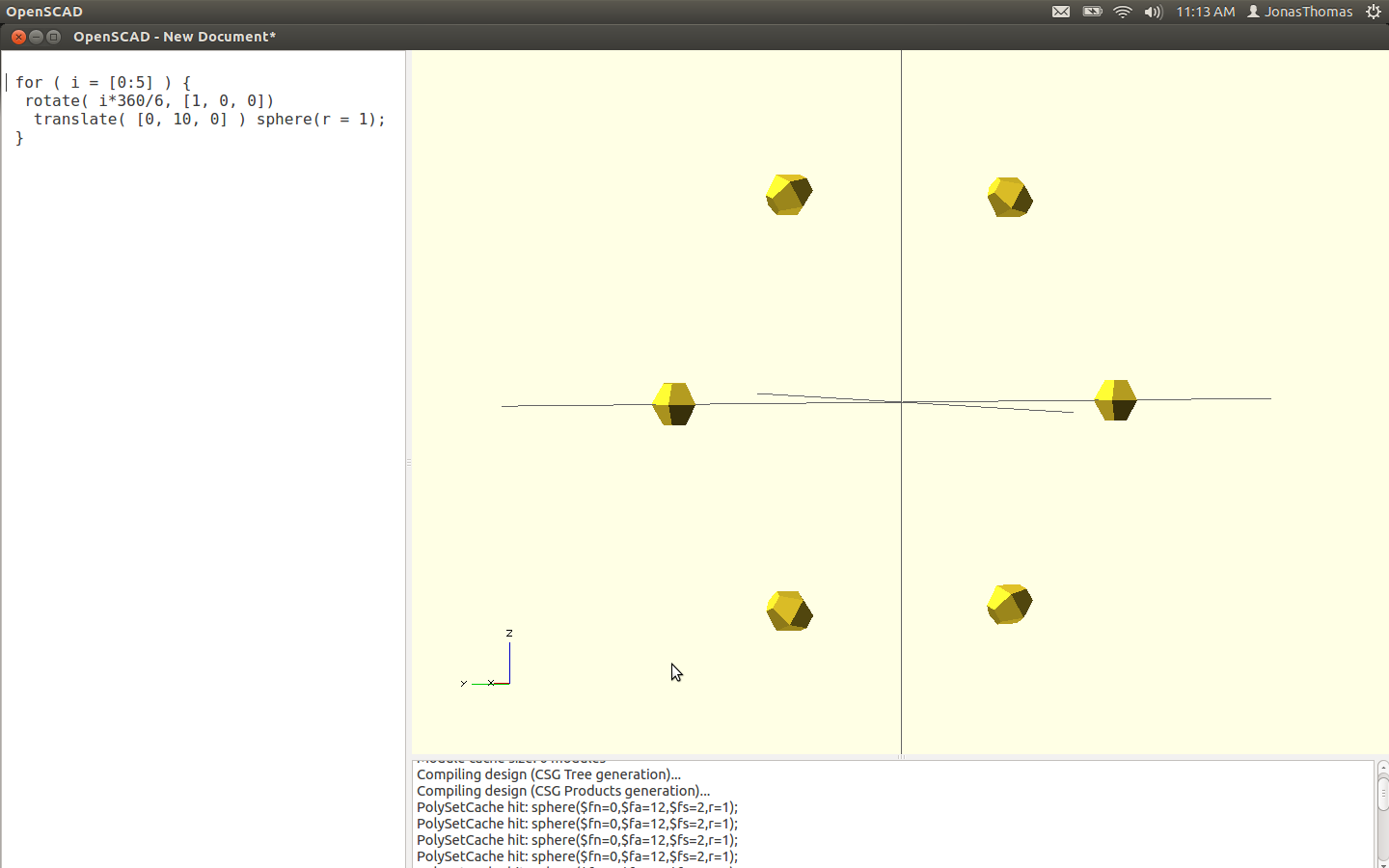
Ok… No I never played with scad before.. I have to admit, its rather intriguing. I’ve been looking at this tutorial running through some of the sample code.
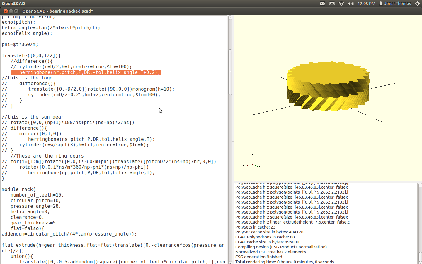
One of the the things I was hacking up was this line of code:
With a couple of pretty minor code tweaks I got it looking like this:
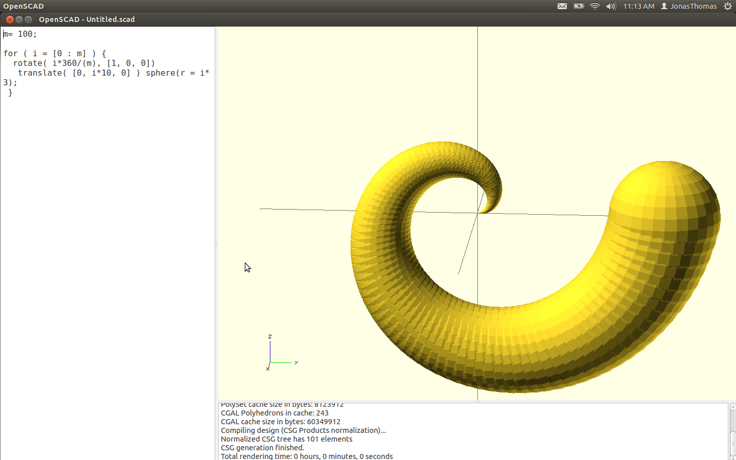
Anyway.. That’s not what this post is about.. I just thought that was cool.
I could see scad being very powerful modelling formulas and stuff…
But I want to get this gear wheel into freecad… So… I’m looking what appears to be the main loop of the program and it has three major components the ring gear, the planets and sun gear..
Soooo. I just want to generate the ring gear. While I’m at it, I’m going comment everything out of a main loop instead of the ring gear.

This is going to take some more investigating.
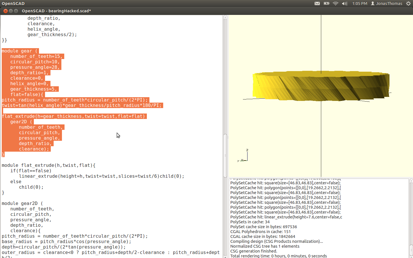
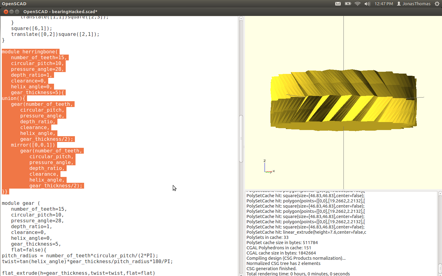
What interesting there seems to be some kind of bug with rendering. It ring gear displays as a helical but if I look at it from the top or bottom the hand changes… Go figure. So what appears to be going on is that a herringbone gear is created and the subtracted from a cylinder to create the ring gear… So if I just display the ring gear this is what I get.
Look at the function call for the herringbone routine it looks like it has default values built into it.. So I’m thinking if I just call that we get…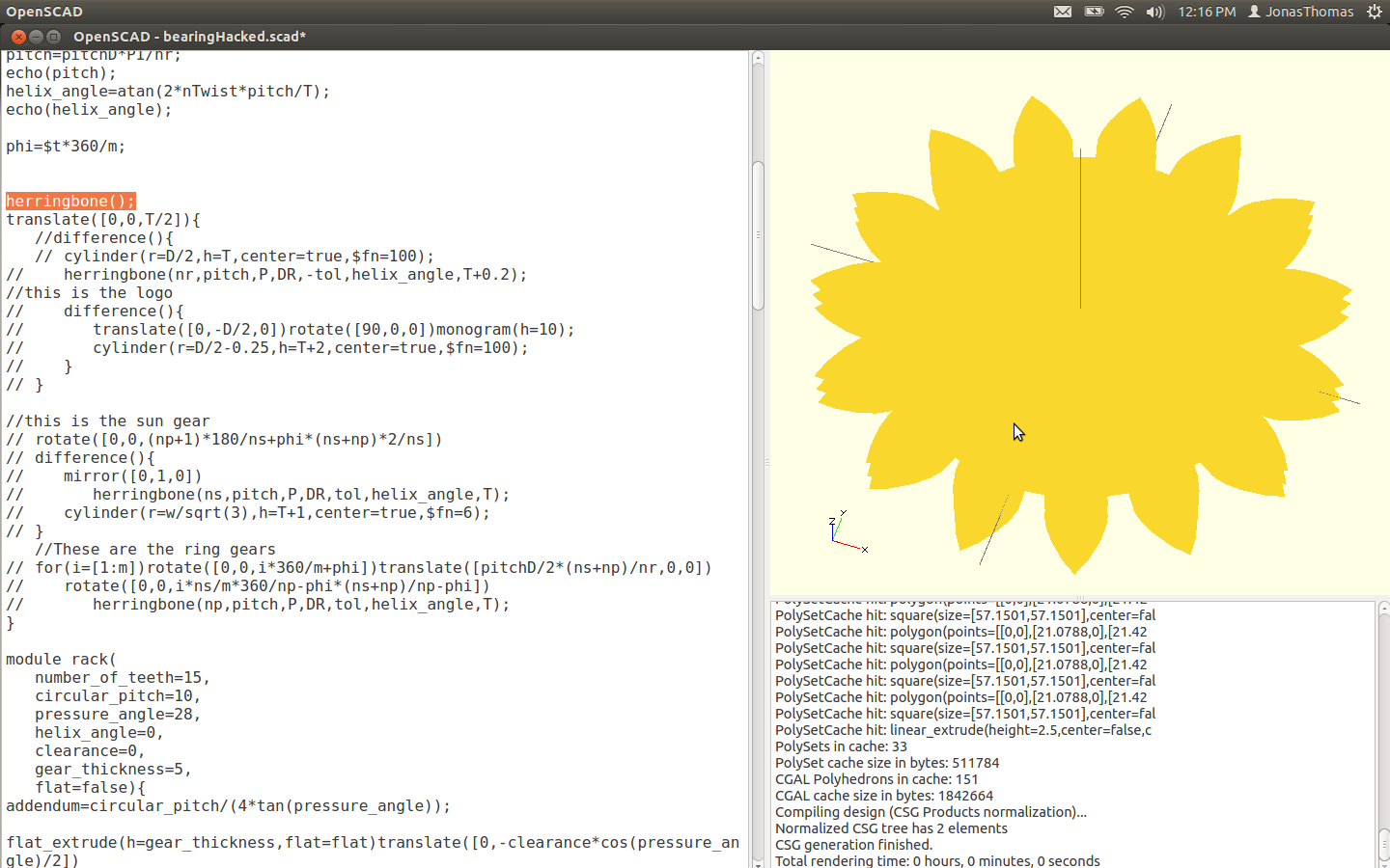
So the next thing here is the herringbone gear used for the ring gear being generated by the ring gear itself.. So what’s going on is 2 helicals gears are being generated and the second one is mirrored and then it’s unioned.
This this makes things rather interesting…
So now I just changed the main loop to:
gear(nr,pitch,P,DR,-tol,helix_angle,((T+0.2)/2));