Reprap woes…

Ok… Things are not going to good.

My Y-axis on my ramps 1.4 stopped working  I’m reasonable certain into not the pololu and it’s not the motor.
I’m wondering if there is some type of weld solder failure in the ramps 1.4 shield or the mega.

I swapped the motors and the y-ran fine in the x and the x didn’t run in the y….
I put things back and swapped pololu’s  the Y-axis pololu doesn’t seem to be running well in the x…

The x in the y doesn’t run well at all.

I managed to burn up one of my Z-axis Pololu’s when I accidentally shorted it out. ( I had a spare)
Then I managed to break the tab on a current pot for the y…  (When I put it in the x.. It ran but irratically… I’m wondering if something is screwed up with the pot.

At the moment I’m thinking that there is something screwed up either with the ramps 1.4 Shield or the Arduino mega…  I was looking at the mega… It looks like it had some rework done on it…

I’m reasonable certain that chip is geting power to Vmot,

http://reprap.org/mediawiki/images/3/3f/Arduinomegapololushieldschematic.png

http://download.lulzbot.com/AO-100/hardware/electronics/RAMPS_1.4/RAMPS_1-4manual.pdf

Posted in Uncategorized | Leave a comment

Working through the issues on getting my extruder running

Some how I didn’t get the memo that I needed to calibrate my Polulu’s on my ramps 1.4.   As this is my first 3d printer that I’m working on,  I can and do forgive myself 😉 .    So this is my research notes page on figuring on how to do that.   In addition, when check my extruder surface temp with my harbor freight laser gauge, I’m checking low, which seems to validated by the high temperatures I need to run at…. (I was toying with the idea of hacking the gauge to read the temperature and then creating an app that would automatically generate the temperature curve… I’m thinking that’s probably been done already if I google enough.) (Hm… one part of the solution is here: http://endless-sphere.com/forums/viewtopic.php?f=7&t=49058

My main drive motor are from Kysan www.kysanelectronics.com Pn 1124090 and here is the Spec sheet http://www.kysanelectronics.com/graphics/1124090-1.pdf 4.2 V Rated at 1.5 Amp/Phase.

My extruder stepper motor is a Wantai Model 42BYGH610 Rated at 1.2 amps 1.8 Degrees pre stephttp://www.wantmotor.com/ProductsView.asp?id=156&pid=80

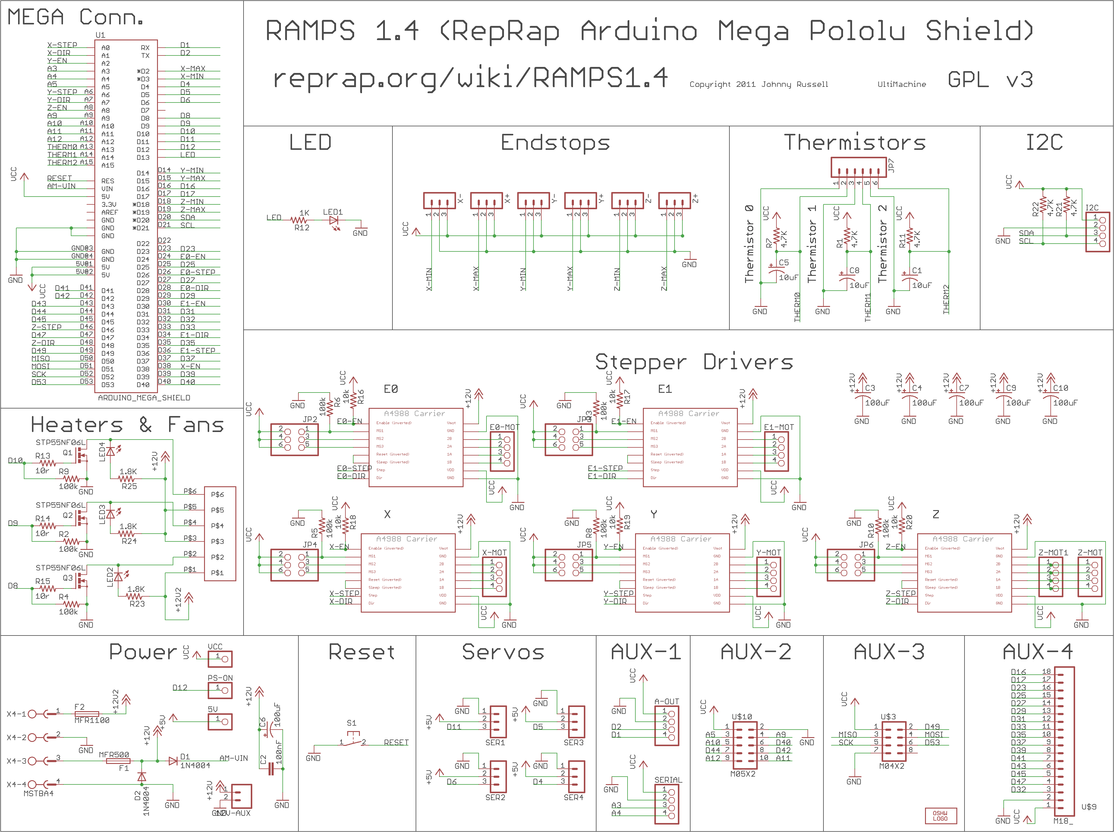
Looking at http://reprap.org/wiki/RAMPS turning the pot CCW lowers the current, CW increased the current.   Not enough the motor wont turn, Too much the magic smoke gets let out…..   That’s good to know.

Soo.. I’m looking at this post  http://forum.pololu.com/viewtopic.php?t=34 and it talks about calibrating the polulo outside on a breadboard and directly measuring the coil amperage setting it at  70% of the rated amperage..  The thing is I need did up a few capacitor and setup a breadboard or by his board for 35 bucks..  Ok… I want to avoid that if I can.

This seems worth looling  at. http://reprap.org/wiki/Calibration

Instructions

Each Pololu has a trimpot located next to the heatsink. The trimpot controls the current that is sent to each motor. Turning the trimpot counter-clockwise reduces the current to the motor, turning it clockwise increases the current to the motor.

Start by adjusting the trimpot down until your motor vibrates on the spot rather than turning cleanly. Now turn the trimpot in a clockwise direction in small increments (1 eighth of a turn) until the motors just start running. Then give the trim port a final turn of about 1 eighth of a turn and your should be good to go.

http://forums.reprap.org/read.php?147,111807,112200

Ok… 1/16 stepping on the motor is NG… try 1/8 http://reprap.org/wiki/RAMPS_1.4#Stepper_Driver_Boards

But back to motor calibration for the moment.
Ok.. Out of google groups I found this link on issues with microstepping: http://www.micromo.com/microstepping-myths-and-realities.aspx

So, I heated up the extruder to where I could push the plastic through the nozzle manually and then I trimmed back the Polulu pot and tried the calibration procedure…
It turned it up and it seemed like I couldn’t get the hobbed gear I made to spin.  I basically had the pot turned up all the way and no joy.
I wound up tearing the extruder apart.  The set screw was loose.  I think the hex in the setscrew  was stripped and I never tighened it enough.   It looks like there was alot of spinning on the shaft.  So I put a setscrew on and really tightened it.   I then tried to set the current on the motor.  This is where things seem to be getting weird..  I could get the motor to buzz when I turn the potentiometer but I couldn’t get it to go. When I manually turned the motor it started turning a bit and then stopped.
I’m thinking its one or more of the following:

Something hosed up on the motor, coils damaged or their not connected correctly.
Something is messed up on the harness wiring.
Something messed up on the Polulu.
At the moment, I visiting Mom for her day… so I can test this out.  I’m thinking the easiest test is to plug in the x-axis motor into the extruder Polulu and see what happens..

Posted in Uncategorized | Leave a comment

DiY MK-7 Gear Hobbed gear experiments. Part II

[Edit] I think that I might be barking up the wrong tree that my gear is slipping on the  filament …  I believe that it is more the case that my extruder is skipping.  The motor hasn’t been calibrated yet.  I reached this conclusion by holding the extruder wheel  with my thumb and tugging on the filament.  No slip… Sooooo. It leads me to believe that I was barking up the wrong tree on this on…. Regardless, I to think a V-notch shape would grip better.  Think V-belts…  But perhaps why I haven’t seen this is that the other solution works good enough??

This a continuation of experiments tried here: http://www.metalshaperman.com/?p=1479

So I was tried making my own hobbed gear using my mill and an spin indexer and I was really rather pleased with the machining outcome… Unfortunately it didn’t work in my qb-db extruder.   I think I used a 10-32 tap and the radius was too big for the filament to grip properly..  I don’t have small metric traps in my in home shop tool inventory, but I to have some small english style ones and plenty of steel to experiment on.   One a side note.   In my first experiments, I machined a radius, to hob into, but I found that I could just plunge it in and it works.  (I wonder if I might be getting some rounded edges because of this, but that might be something I look at in future experiments.

Eyeballing the Qu-db extruder gear and my taps it seems it might be fun to try hobbing the following sizes:2-56, 3-48,4-40

Oth…maybe I should try to be a bit more scientific about this.  I just measured some sample PLA that I got from  http://www.ultimachine.com/ and it mic’s up around  .068″ (1.73 mm) I’m thinking I need the minor diameter of the tap to be some where around there, so I have nice full contact around the filament.   So as that guy David Brancaccio say on marketplace…. Time to run the numbers.

I’m using Machinist handbook 23’rd addition page 1303 as reference.

So.. I need to figure to figure out a shim for my stop in my mill.
I measured the Qu-bd gear OD ~.457″
The slot diameter ~.416
.457-.416/2 = .205
Offset = .205+ thread depth.

Major Diameter Min Diameter Thread Depth Offset
2-56 0.086 0.0804 0.0056 0.205 0.2106
3-48 0.099 0.0928 0.0062 0.205 0.2112
4-40 0.112 0.1052 0.0068 0.205 0.2118

Hmmm.. I didn’t realize that my smallest tap still had a min dia larger than the filament .080 vs .068.   It’s better then what I had before but not really  it the best.
I wonder if I could machine a small V-notch and get it there with a knurl or better yet coat it with some type of abrasive. I was looking at some stuff here. http://reprap.org/wiki/Drive-gear  It doesn’t appear that anyone has tried this… Interesting…’
I was going to make my blanks and use a boring bar to single point the 5mm bore… I think I’m going to invest in a chucking reamer… Something  tells me I’m going to be making more than a couple of  blanks, and it gets a little tedious to  single point these little bores….
Oh well.. The day is gone.. No chips cut, but did have a good day with the family..

I think I’ll fire up the extruder and see if anything has magically changed before bed..[Edit]  Ahhh geezz… I should have just went to bed and left things alone.   It seems that my extruder x-axis is loosing steps all over the place… I did some quick googling and I found an interesting discussion here.  https://groups.google.com/forum/#!topic/deltabot/zUq0C2i18FY

Posted in Uncategorized | Leave a comment

Figuring out how to get the thermistor values into sprinter for my qd-db extruder.

I’m did a little bit of a happy dance the other day.   I managed to get my Qd-bd extruder to poop for the first time.
I got my little wiring breakout board done, and I cut a piece of glass to used double sided tape to get it to stick to the table.   Since my rig mounts to a flat marble plate, I’m going to attempt to not use the springs to preload the table… We’ll see how that works.

Ok… In the initial pooping experiments, I used the default values in sprinter for a 100K thermistor and it seems like I couldn’t get anything to work till I was at 220C.  Soooo… those values must be in the code somewhere.

In sprinter there is a file called thermistortables.h

I made the following hacks and pasted in the values from http://www.fabric8r.com/forums/showthread.php?728-Thermosistor-delta-values-etc:

Ok.. I confused myself earlier but I think I understand things now.

http://www.arduino.cc/en/Tutorial/Potentiometer

So basically the Arduino can measure 5V and bust it up into 0 to 1023. Digital.
So what I think we’re looking at in the thermistor tables here: https://github.com/kliment/Sprinter/blob/master/Sprinter/thermistortables.h  is the digital value from 0 to 1023 on the left side and the corresponding temperature on the the other.
Here’s something I need to look at. http://learn.adafruit.com/thermistor/using-a-thermistor
Ok.. So I have the table resistance from Qb-db now I need to figure out what the resistance is in the Ramp 1.4 Arduino.
According to this is 4.7Kohm http://thefutureis3d.com/images/800px-RAMPS1_4schematic.png

I played around with my tables… And started playing around with a test cube.. But no joy…  It seems like like I’m not getting enough grip with the wheel I hobbed.   I used smallest tap that would fit into an R8 collet.   I’m thinking that  was too large a radius.   I tried the qu-db gear as well and no joy as well.
It seemed like I could get plastic to extrude when I press down on the filament, but my wheel just isn’t gripping enough.
I googled a bit and found something of interest…
http://www.protoparadigm.com/blog/2012/04/thing-o-matic-mk7-pla-set-up-and-troubleshooting-mk8/

Sooo… I think I need to put this aside for a while.. I think I need to hob another gear with a smaller tap..   I have a lassy tapper, that could hold the tap and then hold that with an R-8…  Holding it with a drill chuck is not and option since the side load would push it out of the holder.

Posted in Uncategorized | Leave a comment

More on the QB-DB extruder mods.

Ok.. So I was reading about all the issues people where having with there qu-bd extruders and how they where addressing them.  One issue was roughness in the bore.
I got some lapping compound and I used that  and a round nylon brush to get that all straightened out.   I found a set of very nice nylon cleaning brushes at American Science and Surplus that did the trick for about 3 bucks.    I startedt using the next to smallest brush brush to lap the bore.  Initially when I stroked through the bore it was quite rought and I couldn’t fit the next size up at all.     I stroked it 400-500 times with the small brush with the tube immersed in lapping compound and then I repeated again with the next size brush up.   Thinking about it I wonder if I wore the brushes down or I actually did something.   Hmmm. I have two extruders and…….on the unlapped bore, if I insert the intial brush it goes in some what easier but it’s as if you can feel the burrs inside the bore..  So I feel fairly convinced that my lapping efforts have accomplished something.

I wound up reassembling and I’m at a point where I need to do the wiring   I found the specs for  the motor here: http://www.wantmotor.com/ProductsView.asp?id=156&pid=75&sid=80

I had ordered a ramps 1.4 https://ultimachine.com/ramps-pre-assembled-kit-complete   with the optical endstops.   The kit includes a 36″ 9 conductor, 26awg cable, pre-crimped w/ 1×2 0.10″ 5A connectors/housing for thermistor (x1)

http://reprap.org/wiki/RAMPS_1.4

The wiring color sequence that plugs into ramps 1.4 is Red Blue Green Black.   Ok… I checked continuity on the motor to the diagram and it seems to matches.

I want to isolate the wires. especially on the thermistor from any type of fatigue damage from the carriage going back and forth.   So..  I’m thinking I need a small board to connect the the ribbon cable I got from Ultimachine.   I tried googling to see if there was a board connection

Links for  wire gauge seem to be all over the place. here: http://bestboatwire.com/catalog/includes/languages/english/wire_gauge_chart.html and here:http://www.engineeringtoolbox.com/amps-wire-gauge-d_730.html

This is the guide that seems the most handy. http://www.sunforceproducts.com/Support%20Section/Solar%20Panel%20&%20Charge%20Controllers/WireGaugeSelectionTable.pdf

Then I’ll need to deal with a cooling fan as well http://pomeroyprinting.blogspot.com/2012/09/using-cooling-fan-on-ramps-14.html

So I finally got everything basically wired up…  I found some qd-bd thermistor values here: http://www.fabric8r.com/forums/showthread.php?728-Thermosistor-delta-values-etc
So I suppose they need to be entered somewhere.  Ok… Googling I found this . http://reprap.org/wiki/Sprinter
I think I have the settings  already…

Posted in Uncategorized | Leave a comment

DIY MK7 Extruder gear

I’ve been making my own 3d printer and I’ve finally at the  the point where I can make  use the kickstarter. QU-BD  extruder.
http://www.kickstarter.com/projects/qu-bd/open-source-universal-3d-printer-extruder-dual-ext
The machining on these parts was superb but there where some deficiencies in the design, which are discussed here: http://www.fabric8r.com/forums/showthread.php?793-My-very-own-QU-BD-woes

So it sounds like the path I’m going to follow was cut by Mr. Bart Dring (http://www.buildlog.net/wiki/doku.php?id=ord_bot:qu-bd_extruder_improvements) with my little twist being that I’d  make my own extruder wheel,
I found some interesting information here  on making your own wheel:
http://forums.reprap.org/read.php?70,129894,138574

On cutting a worm wheel I found some stuff here: http://www.practicalmachinist.com/vb/general/hobbing-gear-tap-how-160177/ I’ve seen some discussion that the blank needs to be gashed first in an indexer. (I wanted to see if I can avoid that.)
I have a very nice spin fixture/indexer with a 5c collet.  Initially,  my thought was to place the blank in the indexer on the mathematically correct center distance in my mill to the I’m wonder what would happen if I feed the tap axial instead of radial into the piece.  I’m thinking the worst that can happen is that I snap the tap.   I don’t have a large assortment of metric taps but it seem I’m good on inch, so if I’m going to break  one or two or ???, I want it to be an inch tap.  My hope that since I’m the correct center distance the timing thing should just work itself out.  I wound up doing is just feeding in radially and it seemed to work just find.  This approached saved me the hassle of figuring out/setting center distance.  I not sure it would have worked anyway.

I wound up finding some pretty cool gear links, that might come in handy when I want to actually make a worm gear.  I don’t need them for this project but they where interesting links non-the-less.

Ok.. So I found thread pds here: http://www.osgtool.com/_branding/osgtool.com/files/catalogpages/USCTS08%20314.pdf
Also I found some info on worm gears formulas here… http://www.roymech.co.uk/Useful_Tables/Drive/Worm_Gears.html
Ahh… Detailed formulas here for Metric (http://www.sdp-si.com/D805/D805_PDFS/Technical/8050T072.pdf)

Originally I was just going to use a 6-32 tap as a hob. Unfortunately, I don’t own a R-8 collet and I was in no mood to make an adapter sleeve or get a R-8 collet just for this.
I wound up increasing the tap size till I was able to get it to fit in my R-8 collet.  So I wound up using a 10-32? tap.

The Geared wheel on the the QU-DB extruder is a brass spur gear with a circular slot cut into it.  I figure I maintained the OD of the Gear and the Min Diameter of the groove, I should be ok.. (If not.. I let the moths out of the wallet and get a MK-7 tooth gear.

Basically I have a huge supply of 3/4 steel that seems to machine wheel so I thought I’d try that.  I turned the OD down and cut a groove to the same diameter as the QU-DB gear.  I didn’t bother drilling it and I just wanted to see what would happen.  I was actually sort of pleased with the result although improvement is needed.   The thing that I need to do is to set a stop to keep from hobbing too deep.   A couple of tricks, I help the rotary rotate when the tap first started biting, that seemed to help.  I suspect giving it a good bite (not enough to snap the bit probably helps too.

Experiment number two.
Ok.. I’m feeling lucky.. So I’m going to tap using a 10-32 Thread.  I went wrong on my first attempt in that I didn’t add a stop to control my depth…  So basically I need the whole depth of a 10-32 thread.  Machinist handbook give me a internal thread depth of .019
I measured the Qu-bd gear OD ~.457″
The slot diameter ~.416
So if I touch the tap to the OD of the part.  I need a block to set my offset of
.((457-.416)/2)+.019=0.0395      So If I set with a .010″ Feeler gauge I can use a .050 gauge block to set the stop…

It seems that it worked ok..   If someone wants to see pictures… Let me know an I can add some…. But now I’m to other things..

Posted in Uncategorized | 1 Comment

Trying to get Repartier-host Sprinter Ramps 1.4 to do something.

Ok… I’m pretty sure that the sprinter firmware uploaded to the Arduino.
The default test program I was using was constantly blinking.   That doesn’t seem to be happening any more.
Let me try this once more when I try to upload I get a message Serial Port Com1 not found Retry the upload with another serial port?  And the only option is /dev/ttyACM0   Then I hit ok with this option it seems like things are uploading.

So when I go to connected through  the Repetier host /dev/ttyACM0 I thought initially was is not one of the options….

Update:
It turns out that it was the last option on a very long list.   The answer was in front of me if I had eyes open to see.  Apparently the Arduino IDE searches and lists Arduinos connected and Repartier lists all ports available.
One thing I did understand is why all other ports have tty### and they’re one port ttyACM0. This link sort explains that http://www.rfc1149.net/blog/2013/03/05/what-is-the-difference-between-devttyusbx-and-devttyacmx/

Anyway, the research notes below are pretty much not required, but there was some interesting content in the so I decided to leave them.

 
Ok…..
I did a little bit of googling.
http://forums.reprap.org/read.php?146,170560,170560
I should be able to try gtkterm which will send characters that don’t appear on the screen.
If I have a good connection, a carriage return should return an OK,  M105 should give a temperature report.
Baud rate s/b 115200
Ok.. something about needing to be a member of a dialout group for serial connection.
according to this http://stackoverflow.com/questions/9839988/dev-ttys0-does-not-open-in-ubuntu-12-04-beta

I can test doing this:
jonasthomas@jonasthomas-Satellite-P305D:~$ ls -al /dev/ttyS4
crw-rw—- 1 root dialout 4, 68 Apr  3 21:47 /dev/ttyS4
jonasthomas@jonasthomas-Satellite-P305D:~$ id -Gn
jonasthomas adm dialout cdrom sudo dip plugdev lpadmin sambashare

Ok dialout is not an issue(which I didn’t think it was since I uploaded the firmware to arduino without root access).

This link had a couple of useful blurbs http://blog.markloiseau.com/2012/05/install-arduino-ubuntu/
Talks about using dmesg to figure out what port the arduino is connect to.

Here’s some info on how to connect via terminal: http://playground.arduino.cc/Interfacing/LinuxTTY
Here’s another way to figure out the port: http://superuser.com/questions/361885/how-do-i-figure-out-which-dev-is-a-usb-flash-drive

I’m getting now where fast.   I started arduino 1.0 and load the test routine and my motors are humming.
I then loaded Arduino 23 abd loaded the sprinter software.
With the motors still running I tried to upload and I got this.

Binary sketch size: 20014 bytes (of a 258048 byte maximum)
java.lang.NullPointerException
at processing.app.debug.Compiler.execAsynchronously(Compiler.java:299)
at processing.app.debug.Compiler.compile(Compiler.java:160)
at processing.app.Sketch.build(Sketch.java:1515)
at processing.app.Sketch.exportApplet(Sketch.java:1555)
at processing.app.Sketch.exportApplet(Sketch.java:1524)
at processing.app.Editor$DefaultExportHandler.run(Editor.java:2293)
at java.lang.Thread.run(Thread.java:679)
This link talks about lsusb which is interesting http://ubuntuforums.org/showthread.php?t=1755534

Good stuff here: http://chmodux.wordpress.com/2012/07/05/ramps/

Posted in Uncategorized | Leave a comment

Building Arduino Sprinter from source