Ok.. So I started this macro stuff about 10 days ago. I had to go to see where I am with my goals.
Regardless of whether I do this through a macro or manually, I think the steps would be basically the same in this instance.
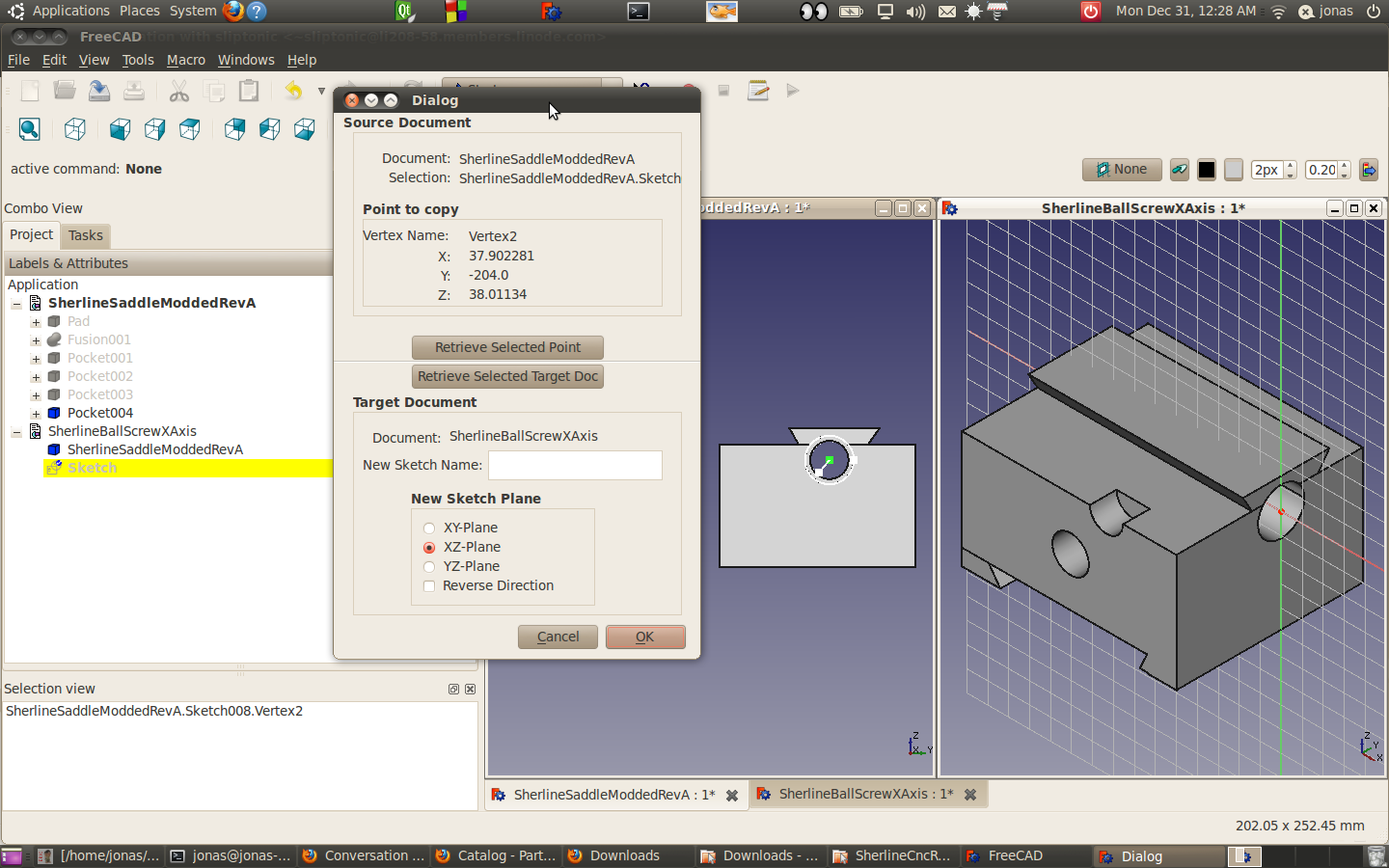
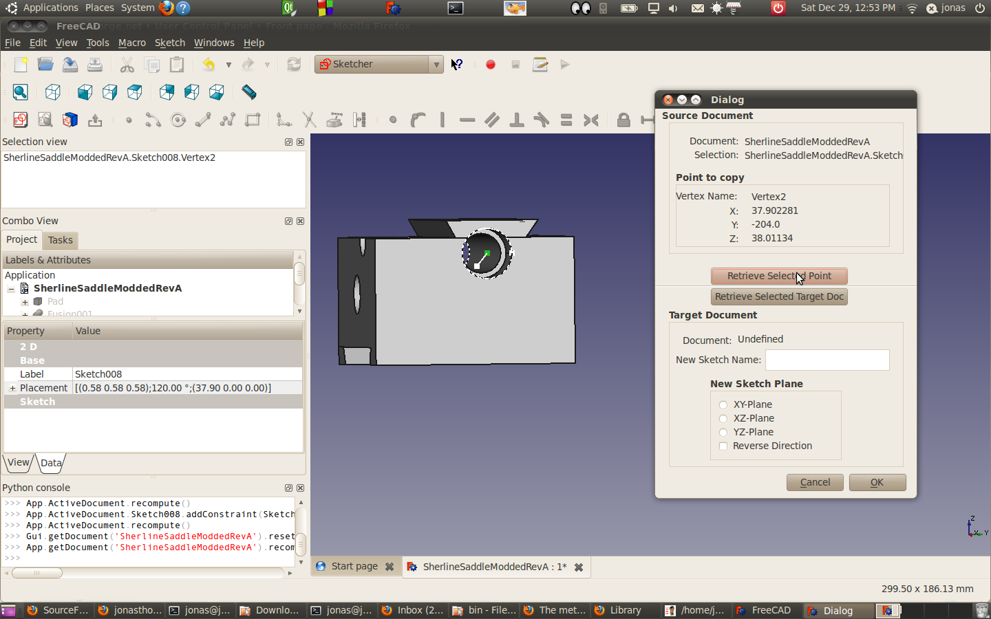
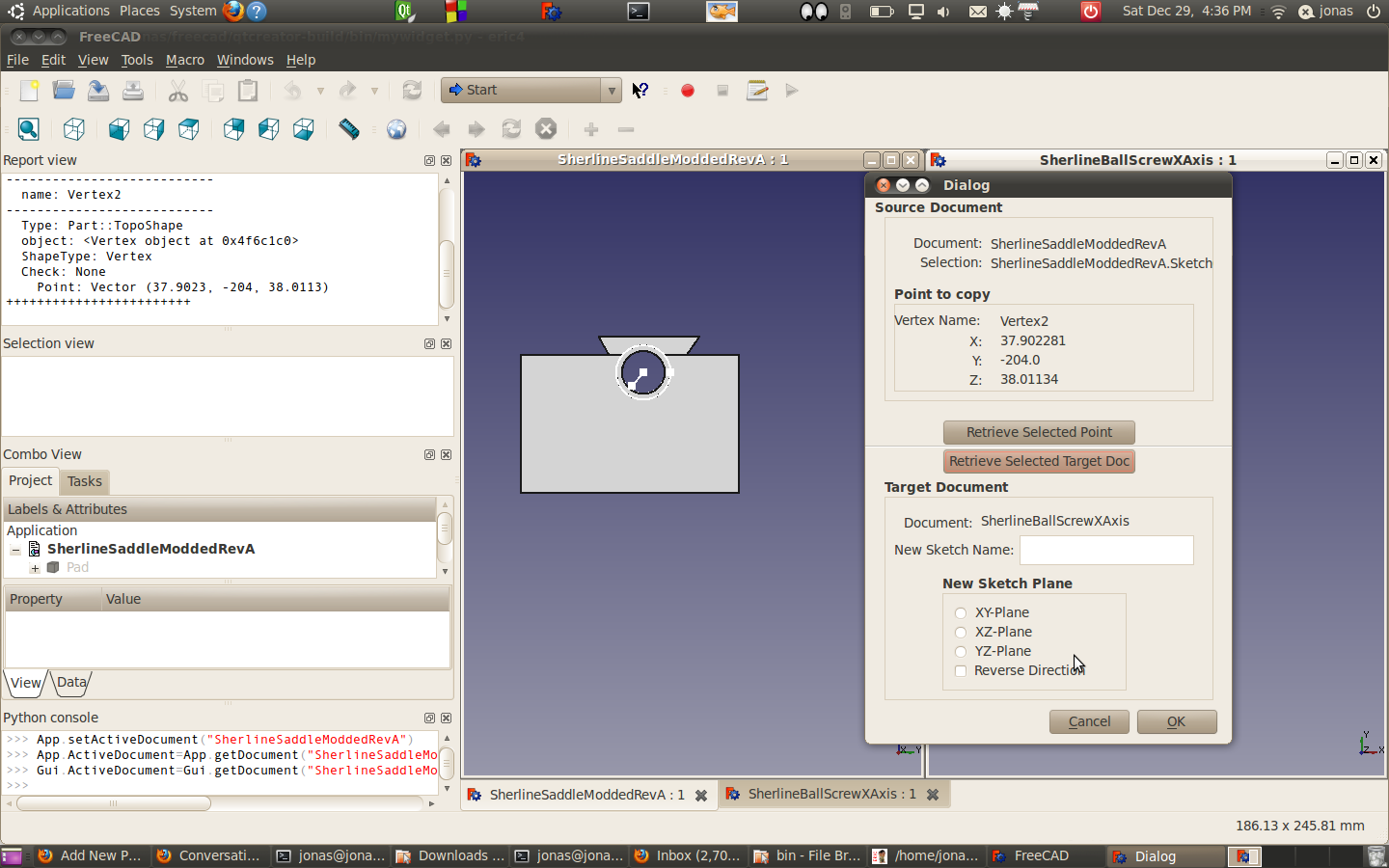
1 Find a point on the sketch plan that needs to be created and save the values.
2) Create a sketch in the x-z plan and offset it so it intersects the point
3) Create a line whose start point on the sketch that intersects the point in step 1(but is not linked to that point) the endpoint and the line are left constraint free while the starting point has a lock constraint applied.
This is taking me a little longer than I would have liked. I sort of would have like to have some chips cut already for the Sherline. Oth I think I have a much better grasp of python, although there is still much to know. Hm see how long this one takes. Hopefully I can just blast through this.
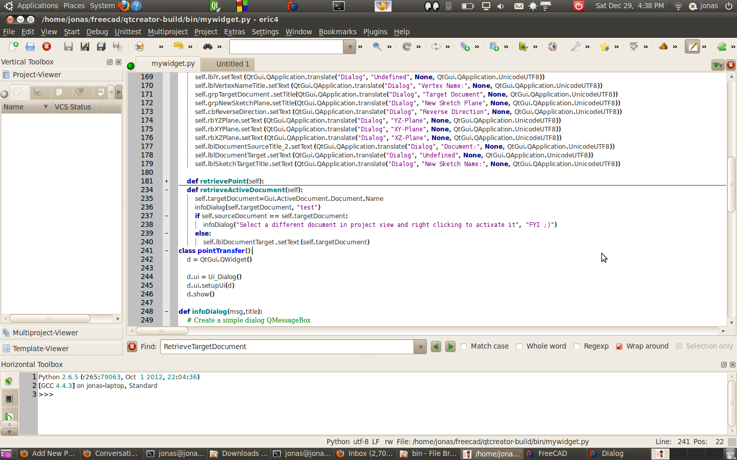
So next I need to programmatically create a sketch in freecad. I could be able to do this through the Gui and it should reveal some of its secrets to me:
Python 2.6.5 (r265:79063, Oct 1 2012, 22:16:31)
[GCC 4.4.3] on linux2
Type ‘help’, ‘copyright’, ‘credits’ or ‘license’ for more information.
>>> App.newDocument()
>>> App.setActiveDocument(“Unnamed”)
>>> App.ActiveDocument=App.getDocument(“Unnamed”)
>>> Gui.ActiveDocument=Gui.getDocument(“Unnamed”)
>>> App.activeDocument().addObject(‘Sketcher::SketchObject’,’Sketch’)
>>> App.activeDocument().Sketch.Placement = App.Placement(App.Vector(0.000000,0.000000,0.000000),App.Rotation(0.000000,0.000000,0.000000,1.000000))
>>> Gui.activeDocument().activeView().setCamera(‘#Inventor V2.1 ascii \n OrthographicCamera {\n viewportMapping ADJUST_CAMERA \n position 0 0 87 \n orientation 0 0 1 0 \n nearDistance -112.88701 \n farDistance 287.28702 \n aspectRatio 1 \n focalDistance 87 \n height 143.52005 }’)
>>> Gui.activeDocument().setEdit(‘Sketch’)
Ok.. this seems fairly straight forward to me except for the four parameters in App.Rotation…
Ohhh. I just stuck in 4 random numbers and this popped up
>>> FreeCAD.Rotation(9,3,3,32)
Quaternion (0.268567,0.0895223,0.0895223,0.954905)
I think the python wrappper is here:
PyObject *RotationPy::PyMake(struct _typeobject *, PyObject *, PyObject *) // Python wrapper
{
// create a new instance of RotationPy and the Twin object
return new RotationPy(new Rotation);
}
Ok.. I’m not that versed on on the python wrapper stuff.
http://free-cad.sourceforge.net/SrcDocu/d9/db3/classBase_1_1RotationPy.html
But I think it basically we take all the constructors in the C++ rotation class.
http://free-cad.sourceforge.net/SrcDocu/d4/d18/classBase_1_1Rotation.html
At the moment I ok with the back that quaternians are used and it’s been setup correctly, since I’m mimicking what’s done with the create sketch dialog I think track down that code and see what it got.
So I want to track down the code that generates this.
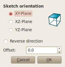
Did a search for Sketch orientation and this popped up
Searching on XY_radioButton should give me what I need…
Yeps… and here it is: http://free-cad.sourceforge.net/SrcDocu/d0/d00/SketchOrientationDialog_8cpp_source.html
Hm.. Interesting, It seems that that was a use of vectors and angles as well a quaternians.. It’s a shame that they don’t have some standard rotations defined. Seems like it would come in handy for people like me.
Ok. I copied the C++ code into mywidget.py and I need to pythonize it. Something for tomorrow..
In the back of my mind, I think I’m going to need another widget tool after I get this one done.
I’m thinking I going to have my sketch plane setup to draw my ball screw shaft… But then I’m going to be snapping points from a punch of different drawings to project on that sketch. That should be an interesting project.
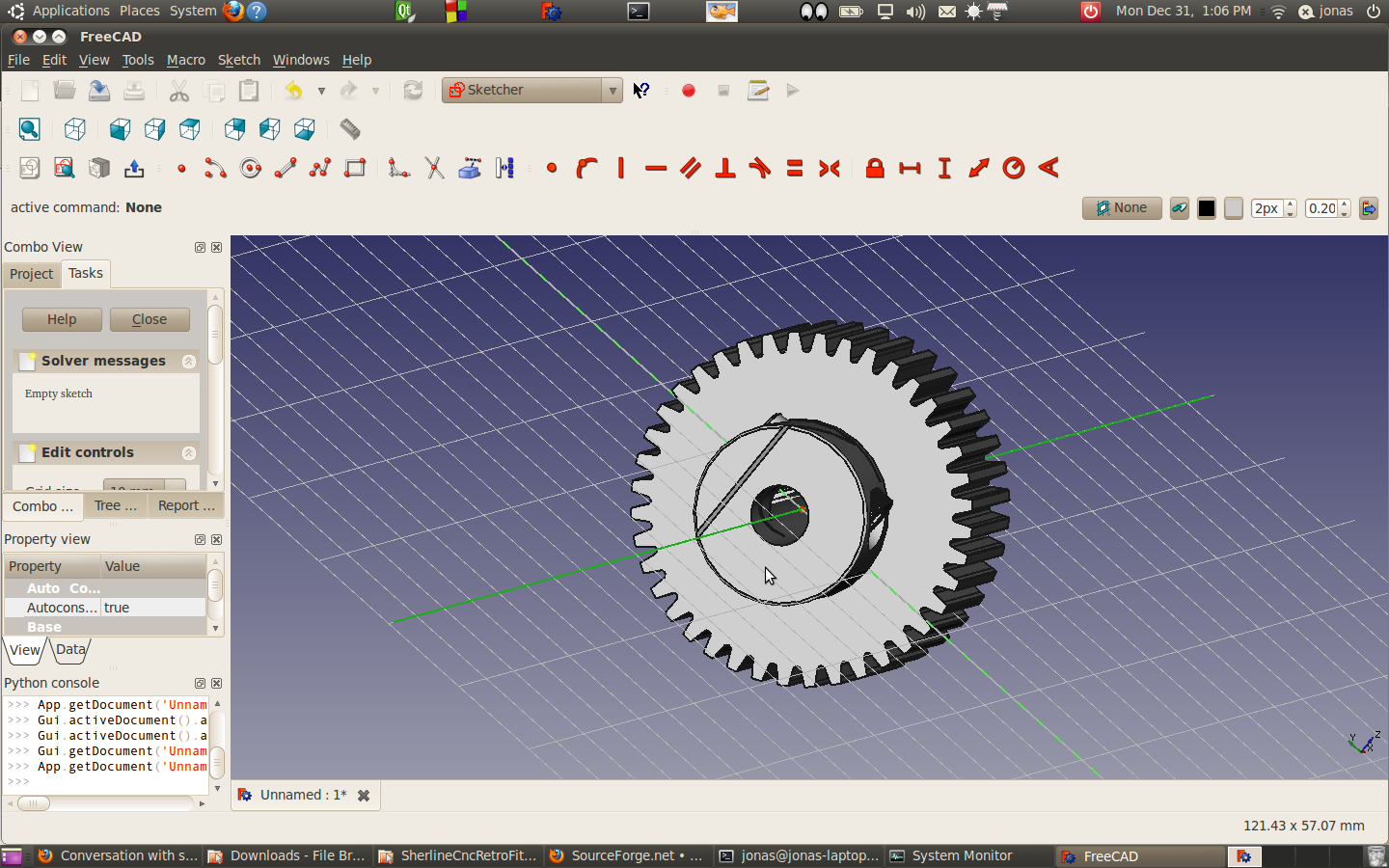 Just for fun, I created a sketch in the x-y plane 0,0,0 and then loaded the step file of the SPD pulley I’m planning on using. It appears that the local origin of the object is centered in the bore (which you’d expect) and the axis of the pulley runs along the pulley. The zero point appears to coincide with the face of the pulley.