Ok… So I thinking I’m approaching a point where the rubber hits the road…. Or not… So… What I’m attempting to do is to add an arc to the polyline mode.
I came up with a sketch for solving the polyline arc

So basically A would be the first mouse click and B would be the second mouse click.
So what I need to do is to solve for C which would be the center of the arc.
Goal:
The goal in this sub-project is to determine the vector position of the center of the Arc “C”. Once worked out, I’m on easy street (in this sub-project anyway) for drawing the Arc in the mouse movement since the code has already been worked out
Figuring out the scalar value of VC what I need to do is to figure out the vector position of C
“A” would be the end point of the previous element and the starting point of the Arc. It would make sense that if we’re drawing a polyline that the Arc should be tangent to the previous element.
That begs the questions… Is there a previous element. Looking at the code, I believe that question could be answered by getHighestCurveIndex(). The question, is that does this return if there is no prior curve?
This function is defined in:
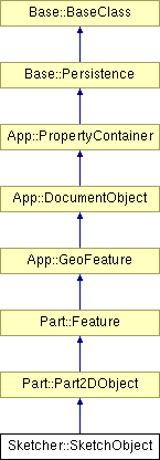
class SketcherExport SketchObject : public Part::Part2DObject
as:
int getHighestCurveIndex(void) const { return Geometry.getSize() – 1; }
Stepping into this:
int DrawSketchHandler::getHighestCurveIndex(void)
{
return sketchgui->getSketchObject()->getHighestCurveIndex();
}
—-
Sketcher::SketchObject *ViewProviderSketch::getSketchObject(void) const
{
return dynamic_cast<Sketcher::SketchObject *>(pcObject);
}
—-
—-
int getHighestCurveIndex(void) const { return Geometry.getSize() – 1; }
—
where Geometry is defined as:
/// Property
Part ::PropertyGeometryList Geometry;

| int PropertyGeometryList::getSize | ( | void | ) | const [virtual] |
Implements App::PropertyLists.
Definition at line 75 of file PropertyGeometryList.cpp.
Referenced by Sketcher::SketchObject::addGeometry(), getMemSize(), getPyObject(), Save(), SketcherGui::ViewProviderSketch::setEdit(), and SketcherGui::ViewProviderSketch::updateData().
int PropertyGeometryList::getSize(void) const
{
return static_cast<int>(_lValueList.size());
}
So… after all that if getHighestCurveIndex returns -1 then there is no preset curve and I need to fake a tangent..
Otherwise I should pick tangent to the last element…
So I think I just need to add a few vectors:
Base::Vector2D centerPoint,tangent,distance;
This is cool check out the Vector2D member functions. There’s a bunch I can use here.
| float | GetAngle (const Vector2D &rclVect) const |
| float | Length (void) const |
| void | Normalize (void) |
| float | operator* (const Vector2D &rclVct) const |
| Vector2D | operator+ (const Vector2D &rclVct) const |
| Vector2D | operator- (const Vector2D &rclVct) const |
| Vector2D & | operator= (const Vector2D &rclVct) |
| bool | operator== (const Vector2D &rclVct) const |
| void | ProjToLine (const Vector2D &rclPt, const Vector2D &rclLine) |
| void | Scale (float fS) |
| void | Set (float fPX, float fPY) |
| Vector2D (const Vector2D &rclVct) | |
| Vector2D (double x, double y) | |
| Vector2D (float x, float y) | |
| Vector2D (void) | |
One thing that I still need to do is to execute a vector cross product. I was have discussion of how to do this on the #freecad IRC and one had showed how to do this in python:https://gist.github.com/2297556
def getTangent(edge):“Returns a tangent vector from an edge in FreeCAD”if isinstance(edge.Curve,Part.Line):vec = edge.Vertexes[-1].Point.sub(edge.Vertexes[0].Point)elif isinstance(edge.Curve,Part.Circle):v1 = edge.Vertexes[-1].sub(edge.Curve.Center)v2 = edge.Curve.Axisvec = v1.cross(v2)else:print “not supported”vec = Nonereturn vec
// This file is generated by src/Tools/generateTemaplates/templateClassPyExport.py out of the .XML file
// Every change you make here get lost at the next full rebuild!
// This File is normaly build as an include in VectorPyImp.cpp! Its not intended to be in a project!
PyObject* VectorPy::cross(PyObject *args)
{
PyObject *obj;
if (!PyArg_ParseTuple(args, “O!”, &(VectorPy::Type), &obj))
return 0;VectorPy* vec = static_cast<VectorPy*>(obj);VectorPy::PointerType this_ptr = reinterpret_cast<VectorPy::PointerType>(_pcTwinPointer);
VectorPy::PointerType vect_ptr = reinterpret_cast<VectorPy::PointerType>(vec->_pcTwinPointer);Base::Vector3d v = (*this_ptr) % (*vect_ptr);
return new VectorPy(v);
}
PyObject* VectorPy::sub(PyObject *args)
{
PyObject *obj;
if (!PyArg_ParseTuple(args, “O!”, &(VectorPy::Type), &obj))
return 0;VectorPy* vec = static_cast<VectorPy*>(obj);VectorPy::PointerType this_ptr = reinterpret_cast<VectorPy::PointerType>(_pcTwinPointer);
VectorPy::PointerType vect_ptr = reinterpret_cast<VectorPy::PointerType>(vec->_pcTwinPointer);Base::Vector3d v = (*this_ptr) – (*vect_ptr);
return new VectorPy(v);
}


Oh… this might be it… duhhh:
tangent.Set(lineSeg->getEndPoint().x-lineSeg->getStartPoint().x,
lineSeg->getEndPoint().x-lineSeg->getStartPoint().y,
0.0);

It’s not up in this picture but I need to fix if the center of the arc is above the line or below the line.
float radiusLength= (Distance.Length())/(2*sin(theta ));

I copied the code for the arc from DrawSketchHandlerArc whose behavior is different.


So.. I think issue 1) is easy…
referring to http://www.cplusplus.com/reference/clibrary/cmath/atan/
and
http://www.cplusplus.com/reference/clibrary/cmath/atan2/
Atan2 returns Principal arc tangent of y/x, in the interval [-pi,+pi] radians.
What I need to wind up with is 0 to 2PI if I’m going to the left CCW and 0 to -2PI if I’m going CCW.
So.. I need to factor direction when I’m calculating the angle… (More on this later)
I had this vector reference bookmarked at work.. It’s a nice site… This really belongs in my useful links, but good for know
http://chortle.ccsu.edu/VectorLessons/vch09/vch09_6.html
http://free-cad.sourceforge.net/SrcDocu/d6/d23/Tools2D_8cpp_source.html#l00036
4-19 update…Getting tanalizing closer… Stupid logic errors that I almost have worked out for the CCW polyline arc. I still done have the mousedown event written to draw the arc, so I revert to line (key up on the “A” to test the next case. Here’s where it’s bombing.

4-21 update. Yeah… Arcs to draw out properly CCW condition. I’m going to get the the code to respond to a hard set clockwise before start working on the CCW/CW selector.

This is the little section of code(Which works at the moment) that caused me such pain, no big deal..
(Just in case I need to get back to this point
// if ((kVec.z ==-1) ){//ccw
if (startAngle<=0 && finishAngle>=0 )
arcAngle = finishAngle – startAngle ;
else if (startAngle>=0 && finishAngle<=0 )
arcAngle = abs(finishAngle+ 2 * M_PI – startAngle);
else if(( startAngle<0 && finishAngle<0 )|| (startAngle>0 && finishAngle>0 )){//somewhere in the 3 or 4 quandrant
if (finishAngle>startAngle){
arcAngle =finishAngle-startAngle;
}
else{
arcAngle =finishAngle-startAngle+ 2* M_PI;
}
}
else
arcAngle = abs(finishAngle – startAngle);
// }
// else
// {
// }
—–
Ok… I think I got the arcs to draw out properly for both ccw and cw conditions. Here’s the magic:
if ((kVec.z ==-1) ){//ccw
if (startAngle<=0 && finishAngle>=0 )
arcAngle = finishAngle – startAngle ;
else if (startAngle>=0 && finishAngle<=0 )
arcAngle = abs(finishAngle+ 2 * M_PI – startAngle);
else if(( startAngle<0 && finishAngle<0 )|| (startAngle>0 && finishAngle>0 )){//BOTH START AND FINISH EITHER UPPER OR LOWER QUANDRANTS
if (finishAngle>startAngle){
arcAngle =finishAngle-startAngle;}
else{
arcAngle =finishAngle-startAngle+ 2* M_PI;
}}
else
arcAngle = abs(finishAngle – startAngle);//Don’t think this point is ever reached
}
else{//cw rotation
if (startAngle<=0 && finishAngle>=0 )
arcAngle = abs(finishAngle – startAngle-2 *M_PI) ;
else if (startAngle>=0 && finishAngle<=0 )
arcAngle = abs( -finishAngle + startAngle);
else if(( startAngle<0 && finishAngle<0 )|| (startAngle>0 && finishAngle>0 )){//BOTH START AND FINISH EITHER UPPER OR LOWER QUANDRANTS
if (finishAngle>startAngle){arcAngle =abs(finishAngle-startAngle- 2* M_PI);
}
else{
arcAngle =abs(finishAngle-startAngle);}
}
else
arcAngle = abs(finishAngle – startAngle);
}rx = EditCurve[0].fX – CenterPoint.fX;
ry = EditCurve[0].fY – CenterPoint.fY;
for (int i=1; i <= 29; i++) {
float angle = i*arcAngle/29.0;
float dx,dy;
if (kVec.z ==-1){
dx = rx * cos(angle) – ry * sin(angle);
dy = rx * sin(angle) + ry * cos(angle);
}
else{
dx = rx * cos(-angle) – ry * sin(-angle);
dy = rx * sin(-angle) + ry * cos(-angle);
}EditCurve[i] = Base::Vector2D(CenterPoint.fX + dx, CenterPoint.fY + dy);
}
EditCurve[30]=CenterPoint;
EditCurve[31]= EditCurve[0];sketchgui->drawEdit(EditCurve);
if (seekAutoConstraint(sugConstr3, onSketchPos, Base::Vector2D(0.f,0.f))) {
renderSuggestConstraintsCursor(sugConstr3);
return;
}
break;
}
applyCursor();}
So… Unless I missed something as far as the arc logic in mouse moves… It’s done…. Now on to setting cw and ccw