So things are moving along on my macro project. My original goals below I have I’ve come to release where flawed. Step 3 is really not necessary when the transfered point becomes the origin of the new sketch plane.
1 Find a point on the sketch plan that needs to be created and save the values.
2) Create a sketch in the x-z plan and offset it so it intersects the point
3) Create a line whose start point on the sketch that intersects the point in step 1(but is not linked to that point) the endpoint and the line are left constraint free while the starting point has a lock constraint applied.
 The basic logic in the widget is functional but it needs to be improved on. I need to think on this a bit.
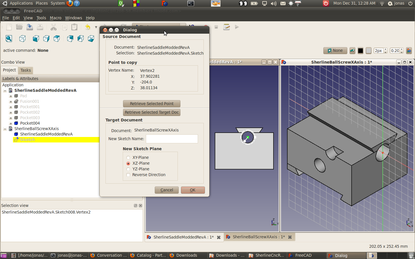
In review this is what the widget does in this instance.
I have my freeCAD solid that I programmatically extracted and stored the center point coordinates on the circle that’s used to make the counter bore in the saddle.
I had a blank document (SherlineBallScrewXAxis) that I selected in FreeCAD and I clicked on the “Retrieve Selected Target Doc” with identified where I wanted to create a sketch. (I’m going to draw a ball screw in cross section and then use revolve to generate the solid). So basically what I did was take the coordinates in the one document to make that the center of a new sketch in my specified target do with a user specified plan.
Initially I thought Id need a line with a lock dimension on the first point. What I didn’t consider is the origin of the sketch is point selectable, so that eliminates the need for step 3.
Next thing that I need to do is place the bearings, to help me draw out the x-axis shaft.