
The thingiverse paper crimper http://www.thingiverse.com/thing:17634 was some what disappointing to me… I was experiencing some pretty signficant size variation between the pins and what they fit into also it seems that my z-axis optical endstop is drifting the the position of my table is being moved when I try remove a stuck part from the table… Part sticking has not been an issue other that parts probably sticking too well. Reading through the thingiverse comments it sounds like there’s minimal sizing issues. I’m thinking that I really need to print a full calibration cube to see what I got going on. I loaded up the pins an a gear in freecad and assembled them… Seems like clearance is ok.. Is it leaning towards a calibration issue..
Anyway the subject of this post was fine height adjustment of a z-axis. The problem is that on my printer it’s a pain to do fine Z-height adjustments on the optical endstop. I want to be able to easily raise or lower in .001 increments.
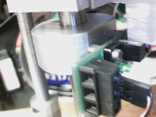
The plan is to create another split adapter and place it below the one shown in the picture and drill and tape both the upper an lower with concentric threas.. The plan is to put a double ended thread rod assembly each with slightly different pitch on either end. The bottom adapter would fixed to the rod and the upper would allowed to float during height adjustment mode (fixed otherwise).. Think of it this way… both split adapters had the same pitch threaded hole and I turned in a threaded rod, there would be no relative motion between the two adapters.
| 1/4-20 | 1/4-28 | 6mm X1 | 6mm X1.5 | 32TPI | ||
| 0.05 | 0.0357142857 | 0.0393700787 | 0.0590551181 | 0.03125 | ||
| 1/4-20 | 0.05 | 0.0000 | -0.0143 | -0.0106 | 0.0091 | -0.0188 |
| 1/4-28 | 0.0357142857 | 0.0143 | 0.0000 | 0.0037 | 0.0233 | -0.0045 |
| 6mm X1 | 0.0393700787 | 0.0106 | -0.0037 | 0.0000 | 0.0197 | -0.0081 |
| 6mm X1.5 | 0.0590551181 | -0.0091 | -0.0233 | -0.0197 | 0.0000 | -0.0278 |
| 32TPI | 0.03125 | 0.0188 | 0.0045 | 0.0081 | 0.0278 | 0.0000 |
This table was created to see what the pitches for common threads an what the differential would be subtracting them..(I was really tired when I did this, so if someone is going to use this please double check the numbers) The smallest move I could get was about .0037 between a M6 X1 thread and 1/4-28
I think I like 1/4-20 an 6mm-1 I combination for a couple of reasons:
- should get a differential movement of about .0106 per rev which is close enough to put a 0 to 9 inch dial on.
- I have both thread rods/taps in stock
- I shouldn’t run into the upper bearing block while making adjustment
So thats it for about now.