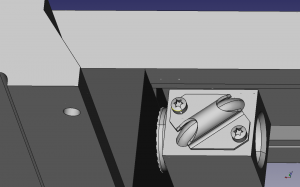
I thought I had my saddle and z-axis rail modifications looking about how I want them. That got me looking at the next step at making the bearing mounts for the ball screws. In the process of writing this post I game across some minor flaws. Basically I’m going to have a clearance issue between the tapered gib and the ball nut on the x-axis. In addition, not really a flaw, but I didn’t think about it, I’m going to loose a small amount of travel on the x-axis. Also, I had some issues with my pulleys coming about the table.
I was poking around the Nook website for inspiration.
http://www.nookindustries.com/Nook3DPS/index.cfm?action=model&model=BallLeadScrew
http://www.nookindustries.com/endmount/EndMountCatalog.cfm
In one of the pages of Nook, they say it is not a good idea to mount the ball tube return upside down. Up is the best, side is secondary and upside down is a no-no. (I kind of thought that but chose to ignore that since it fixed my clearance issues)
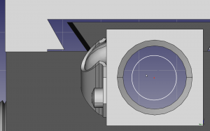 When I rotated the nut 90 things start getting really tight. The issue that I’m having is that I think the tapered gib and the ball tube return are going to get in the way of each other. I don’t want to translate the axis of the x-axis leadscrew. If I push it down, that means I need to push the y-down. The thing is, that I was going to use the existing saddle as a template to set the angle it move the tapered gib so I don’t want to move the gib to the opposite side. Actually, this sort of cool that I’m modelled this before cutting chips. I think the solution is that I flip the ball nut on the opposite side. It just dawned on me that if I want to keep the full travel of the original Sherline, that I would need to have the screw stick out past the end of the table equal to the length of the ball screw.. Well, that’s not going to happen, so the x-travel is going to reduced by the length of the ball nut.
http://ixian.ca/server/timing_belt_specs.pdf !!! On this site this guy machines his column in his lathe. Which is a really good Idea. I was at a loss on how I could do this with the equipment I have. This sight is really interesting and he has done a huge amount of modding. He doesn’t want to be linked to unfortunately and I’m now getting redirected.
I have a bunch of small 16 tooth timing pulleys on hand. So… to keep costs down its going to be what I use. Doing a little research I’m pretty sure I have a 6A53-018DF0908 . The original system had a 1/4-20 rod.. One rotation = .05″/Rev The lead screw 5 threads/inch which = .200″/Rev
05 Inch/rev
————– = .00025 “/step which is in full step.
200 Specs
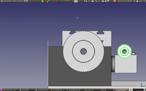 If I want with the same reduction as a 1/4-20 screw lead screw, I would need about a 4:1 reduction. I was able to find a 62 tooth pulley from SDP, which would do the trick.
To get down to .05/Inch .2/.05 I need to a reduction .25 which means a 64 tooth pulley. The closest I can get is is a 62(Aluminium) or a 60 Pulley Plastic. When I did a preliminary layout of the pulleys, I didn’t like what I was seeing.. The pulley OD of the table is way too close to the top of the table. The belt will probably bring it over the top. So, I don’t think that’s going to work.
I figured that sticking with the same reduction was a way for me having to deal with whether my system has enough ompth.. Using a ball nut and ball bearing support is going to be significantly more efficient then what I had going on before this,so I think I have a little bit more lattitude with the reduction. I was just going to go with this, but heck, I run a quick calculation.
Ok the existing sherline system is a 1/4-20 threaded 60 V-thread rod. This is entirely appropriate for a hand cranked manual mill, but this thread form isn’t exactly helping the cause when you having motors driving the system. I initially thought about retrofitting with a acme thread but ball screws are far cooler and more efficient.
I don’t feel like doing an exact calculation but figure 1/4-20 has a pitch diameter of .2175
Assume a lead-screw coefficient of friction of .15 and a lead of .05″. I found a on-line calculator which when I plugged in the numbers I got 32%. I’m thinking this calculator and the lead-screw coefficients are based on acme threads so the efficiently if probably even worse with a V-thread
.2″/Rev * (Rev/200 Steps) *18/36 = .0005″/Full Step
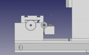 The efficiency I see quoted for Ball screws is 90%. So I’m thinking that if I reduce the pulley ratio 50%, I’m still going to have the same resultant pulley force, plus I’m going to double my rapid speed (Works for me). The only downside is my loss of step resolution, which I don’t think is that big of a deal, since I have micro-stepping with my driver. But still It would be nice to have that step resolution. Once of the things that I noticed is that the bore size shrinks with the smaller number of teeth.
I have a bunch of bearings that I stripped out of roller blades that want to use. The bore size is .3125 with OD .867. The 62 tooth pulley had the same bore size as my bearings which would have been a problem. Soooo. I’m thinking .3125 bearing with a 5/16 -24 thread that I can retain the bearings… Minor diameter on the thread .260.
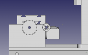 Here’s my optimization, I’m using on hand roller blade bearing (5/16 bore) and 18 tooth 3mm pitch 9mm wide GT pulleys that I have on hand. So I need a .250 pulley bore with something less than 62 teeth so I have clearance from the top of my table. And while I’m at it, it think I’m going to go with the Fairloc feature.. Poking around the SDP web site, I found a 40 tooth A 6D53-040NF0908 for $11.86
So I need to figure out the center distance. Here’s an on line calculator http://www.sdp-si.com/cd/default.htm

