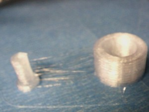
I make a little how cylinder in free cad and printed it out and measured it. Hear are the results
| DRAWN IN FREECAD | ||||||
| MM | INCH | Measured | Measurement method | Comment | ||
| Hollow cylinder | ID | 11 | 0.4331 | 0.399 | Gauge Pins | Huh? |
| OD | 17 | 0.6693 | .669-.680 | Digital Veneer | ||
| LENGTH | 10 | 0.3937 | .395 -.400 | Digital Veneer | ||
| Pin | OD | 0.196 | .208-.214 | |||
This is not what I expected… I deburred the ends of the bore with a chamfering tool and then inserted a gauge pin such that it had barely went on freely.
The gauge pin is much closer to 10 mm ( .3937) than it is to 11mm. At first I thought I misnamed the model, so I went back to check how I dimensioned it… R =5.5 mm
So then I overlayed the Stl over the sketch and it showed that it meshed. This makes no sense to me at all. I’m a full mm off on my bore but the od is ok.
I know that when I drew this out originally I used 11 R and 17 R on the radius, which I immediately killed the print and when back to my Freecad computer and fixed that uploaded the stl file and then downloaded to my printer computer… I overlayed the STL to the sketch and it matched… I’m thinking I messed up somehow and I need to redo the freecad sketch pad the stl etc… and see what happens…. Although for the life of me, I don’t know how I did that…
Anyway… way too tired tonight to mess with this… What I wanted to do was do a little research why my nozzle keeps scraping on my table in my first 3 layers and then causes a motor skip… But the sandman is here…
Just a quick update…. I did a quick search on the search terms… “correlation between layer height and nozzle gap reprap” http://forums.reprap.org/read.php?1,131648
and this discussion thread popped up on the top of the list…. Die swell… Ok…. thats a new one on me…. I need to re-read that link over some morning java… Why is it the more I learn the less I seem to know.? Machining in metal seems way more straightforward to me, as opposed to pooping plastic…

