So there have been a couple of issues that have been bugging me in my last series of prints that I want to do a full 20 mm calibration cube.
One thing was some sizing issues on some model I downloaded from thingiverse. Basically there where some pins that where coming out way thick for the gears they went into.
Also it seems like the center distance was a little short when the gears where pressed together with a little backlash.
Another issue I was having was when I did a manual z move to place a gauge block it seems like I was coming up short…
So… this is a calibration cube I decide to go all out and break out the gauge blocks.. When I had to build up blocks I usually just figured it out without any particular algorithm… I ran across one here. http://www.northerndtool.com/gage-bloc
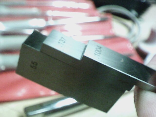
The algorithm is pretty simple basically calculate your size to 4 places… So… I need 20/25.4= .7874″ What you do is find a gauge block to zero out the .0004 so… .1004 and subtract, repeat with the .001 and then the .01
Soo
.7874
-.1004
———
.687 .687 .687
-.117 .127 .137
——– ——- ——
.57 .56 .55
.55
——
0
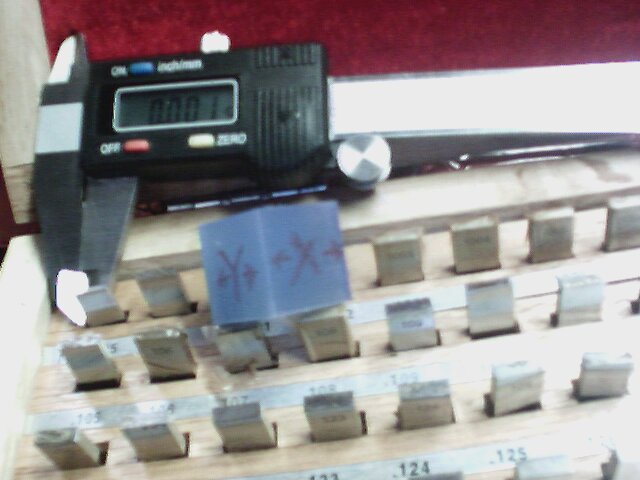
So you make sure the block are lean and they should stick together by themselves.
When I check them against my harbor freight verneer I get .787 to .788 Anyway… I to tired to read the OD mic tonight… So I’m just going to zero out the vernier to the Gauge block and see what the variations are.
measuring along the x-axis parallel .002 -.005 to the layer… Perpendicular to the layers (avoiding the bottom smooshed lather .012-.150 (I think I might be picking up an out of square condition.
Y-axis. .003-.007 (parallel to layer .005-.007 perpendicularly measured across the vernieer.
Z-axis .000-.006
Actually I’m quite pleased with this… I think the table sinks a bit.. I’m thinking if I correct that I could get something a little tigher
I think I might be see some out square with my z-axis.. which is the weak point in this iteration the rockbot.. I’m thinking one more test in the morning I’m going to print out a hollow cylinder in a range that fits my gauge pins… I’m going to draw it in freecad so It’s a known size and then run a test…
11 mm bore should work…
Hmm. While I’m at it I have a left over base from that thingiverse part… It takes a .196 pin… I’m going to draw a .196 pin in freecad and see where that prints out at. But that’s for another day.