
Previously, I had done a quick recalibration and set parallelism using a set of feeler gauges between the nozzle and blue tape. When I had printed out the halves of the Despicable me http://www.thingiverse.com/thing:34204, I discovered quite by chance that my x-axis was not has parallel with the table as I thought. The character was printing in two seperate halves.. On the first 3 layers I noticed that the half on the center of the table printed nicely, while the right side (from my perspective) had squiggly lines. I’m thinking that the z-height distance between the tip and the table was slightly longer their.
At this point, I wanted to see if could get a feel for what the heck was going on. Since at this point, I’m not interested in setting height, I stripped off the blue table to work off the datum.
The feeler gauges should of worked, perhaps I was in too much of a hurry, or the blue table caused some issues. I was thinking about using a dial indicator, but it would be awkward.With the gauge blocks I can go down to .0001 height differences if I need to.
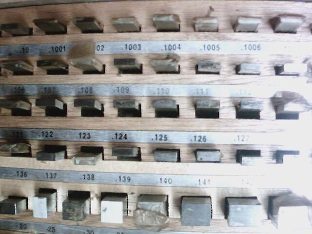
Gauge Blocks
 Just to get started, I homed the z-axis and I had a gap in excess of .030″ with the feeler gauge. I want to zero out to a .120 gauge block which is in the middle of my .001 range blocks.
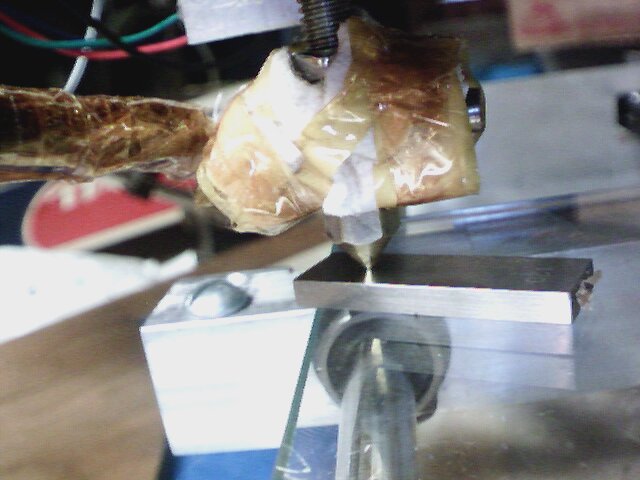
So… I jogged the z to where the .120 when smoothly and the .121 had the slightest resistance. I then disconnected the z-axis motors from Ramps and jogged over the x to the other side.
Now this was surprising to me.. The right side (from my perspective) the side that produced the squigly lines was less than a .120 gauge block. I was anticipating it was going to be more.
So… time for a more exact measurement. Wow… .102 went. .103 had resistance… Yikes… .018″ that’s alot…
So I went back and forth a few times on the x-ax
is to get everything set to .120 go .121 no go.
So… Once the one side was zero’d out. I had a bit of a scare when I reconnected the z-axis motors… Nothing happened.. I thought for a amount that I had either fried a polulo or worse messed something up on the ramps… I was in a bit of a panic, until I powered everything done computer, arduino and brought it back up… It seemed to worked fine… In hind site, I shouldn’t be disconnecting/reconnecting motor with the power on… dumb dumb..
So with the Z-height trammed in on one side of the table, I tested against the opposite side. I seems that I have a downward slop along the y-axis of about .003 left side .004 right side. I think that’s pretty darn good actually (sounds of me slapping myself on the back)… I took great pains to make sure I machined my components accurately and precisely. When I put together the table, I just tried using double side tape with no table adjustment features… I suppose at some point, If I want to correct for .003-.004″ I could do that, but for now… I think that probably meets most of the repraps out there.
Conclusions and lessons learned: My z-height needed adjustment. Gauge blocks on glass are really nice to use for adjusting height. You can easily set height to w/n +-.0005
Things for the future.
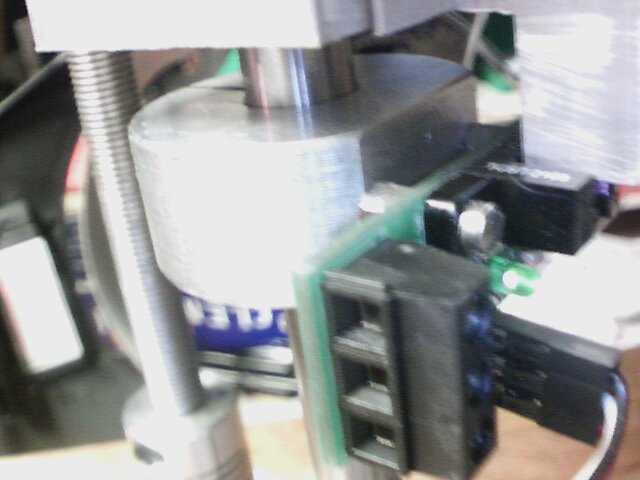
Setting my z-height is sort of hit or miss. Currently I don’t have direct fine adjustment for the z-height. What I was doing was either doing it by watching the light strength on the sensor or using height blocks in the gap between the split bushing and the z-axis bearing block. Seems like there could be some improvement there.
Quick addendum. I wanted to do a quick height calibration.. I want .006 on the high side of the table… So I want to zero out and offest .120 and have it take a .126 gauge block. on blue tap..120 = 3.048 mm… Hmm Something not correlatting… I wonder if something is messed up with my z axis step settings… Uggg. Something for another day.