I just got done attending Musecon this year. I had a great time but scheduling didn’t let attend all three days. When I visited Dale and Dwayne of 2DKits and I saw they had some robot kits that they where trying out for the first time. It’s been something I’ve been thinking about so I got one.
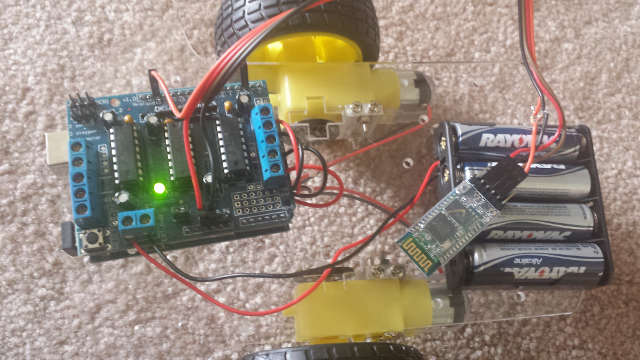
It’s a basic setup but it was pretty easy to get going so that was fun. Components from China, the motors and frame where in shipped as one sub-kit and the Arduino uno and Adafruit motor shields where clones as well as the blue tooth adapter came was added by 2dkits.
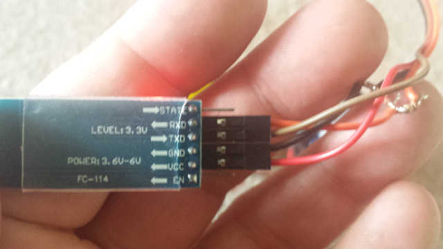
The blue tooth module needed a small hack with a voltage divider to get the signal down from 5 to 3.3 volts.
We also hacked up the motor shield clone to add some pins for the blue tooth module..
The motor shield appears to be a clone of the adafruit v1 motor shield with some details that can be found here.
I want to slowly add a bunch of stuff to this system to create a swiffer bot. Basically, I have alot hardwood floor in my house and having a roomba do it all seems somewhat inefficient. What I’m thinking about is having this bot, drag a swiffer pad behind it. When it reaches one end of the house it would lift the swiffer slightly to deposit the dirt where it could either be roomba’d or done by hand.
So… I’m thinking I want to 3d print out a nicer fitting base, and add motor encoders(just because) a servo to lift the swiffer to start. If I don’t get bored or distracted by life, I won’t mind mounting a ping sensor on a another servo.. That’s a ways away though..
For now I just wanted to understand the motor board layout and how it worked. Basically has 4-H-bridges (via 2 L293D chips) driven by a 74HC595N Serial to parallel output latch.
When reviewing how the latch worked, I ran across this video which I thought really explained it well:
So now, as far as a basic function on a basic motor control using an h-bridge, I thought wiki-pedia explained it pretty clearly. https://en.wikipedia.org/wiki/H_bridge
I’m still a little fuzzy on how the L293D physically works as an H-bridge, but as far as hooking it up, it’s pretty wheel explained here.
Ok.. Now what I’m curious about is how the 74HC595N Serial to parallel output latch relates hooks up to the L293D’s.. I pulled this from here: https://forum.arduino.cc/index.php?topic=211225.0
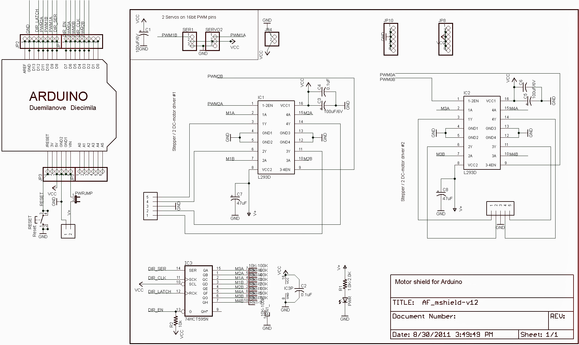
So basically the 74HC595N is sending is sending out the 2 bits to each motor control 2*4 = 8 bits. Ok. That makes sense. I’m out of fun time, but I think I need to take a closer look to figure this all out as far as how this the arduino pins all get assigned out.
I’m thinking my next step is to figure out how the pins get assigned out and then figure out how the optical encoder works.