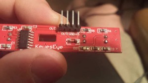
The little robot I picked up a Musecon came supplied with an optical encoder disks but lacked the transmissive optical sensor with phototransistor output, photo sensor, or whatever you call those things. Dwayne had a sensor for paired robot wheels that I got from him, but they were not wide enough to fit the laser cut plastic of the kit. I had a heck of time finding the magic search terms for Ali-Express to potentially find an exact match to the kit. I did manage to find the magic incantation eventually, http://www.aliexpress.com/item/Velocimetry-sensors-sensor-module-encoder-barrowload-speed-robot/1266192518.html
For now, I think I’m going to just doing to 3d print a new platform to match the photosensor sensor span I have and well as optimized it to the mission of my bot. Its mission basically to swiffer my wood floors and drag the stuff to one end of the floor to be picked up by something else. At this point, I think I want my bot to drag a swiffer pad behind it and have a ping sensor in front of it connected to a hobby servo to perform a sweeping scan.
I think I need the speed sensors to help keep the bot moving on a straight line. When it reaches one end of the floor, I want to lift the swiffer off the floor so the dust stays at one end.. (At this point I’ll either just pick it up with a dust pan, or have a Rhomba just focus on that). One thing, I haven’t worked out is how to map objects in the room, and to map a path.. (The ping I think can avoid crashes, but I don’t think it’s enough)
Anyway this is the velocimetry I got to play with at the moment. It was labeled as KeyesEye. I did a fair amount of googling to find a spec sheet but came up dry.
The photosensor is labeled as MOC70T3.. I couldn’t get a match on the T3 but I think this is close enough. http://www.alldatasheet.com/datasheet-pdf/pdf/53870/FAIRCHILD/MOC70P3.html so… it guess the correct term is to describe the sensors is PHOTOTRANSISTOR OPTICAL INTERRUPTER SWITCH.
The main chip on the board is labeled:
74HC14D
L3D8T208
Un01345F
I got a hit on the first number http://www.nxp.com/documents/data_sheet/74HC_HCT14.pdf Hex inverting Schmitt trigger. So basically at then end of all this, I should basically just be able to plug this into an arduino and it should just work.
So I’m interested in figuring out how to setup some type of PID for controlling two DC motors using my arduino, googling I came up with a really cool link for a diy baby segway (which is way more complicated that what I’m interested in doing (at this point anyway) http://forum.arduino.cc/index.php?topic=8652.0
So.. I think for my little project, I’m going to be generating some interupts from the Optical interrupters to keep this puppy driving in a straight line.
So the project at this point, is going to be using a bluetooth module, 2 dcmotors, two servos, one ping sensor, and photo sensors.
I’m thinking about generating a hardware interupt with the encoders to keep track of speed control… Some quick googling gave me this. http://playground.arduino.cc/Code/Interrupts So on a Uno 2 external interupts IntO, Int1 are available on Arduino pins 2&3 Ok.. let me check. Dang, pin 2 is apparently being used by the bluetooth module, so that life slightly more complicated. Although, I have pin change interrupts available.
So I think my next steps are to map out what pins are being used what’s still available, do a little more research on interupts, and PID for DC motor control and try to get a hold of the source that’s currently driving the little bot. After that or before, I should layout my new base for my bot and print it out.
(Interesting link here on PID stuff. http://web.csulb.edu/~hill/ee444/Lectures/08_PID%20Control.pdf
As well as here: http://www.csimn.com/CSI_pages/PIDforDummies.html
And there is this here…
http://playground.arduino.cc/Code/PIDLibrary
And there is this fun little video which I keep coming back to.
http://makezine.com/2008/11/04/using-a-dc-motor-as-a-ser/

