I’ve had the need for bending pipe in freeCAD. I had mentioned this on the IRC as well as the freecad forum. NormandC had posted a video on youtube on how to do this using Dwires.
I’m not sure what Navigation styles he’s using. I’ve been studying his video and I’m trying replicate what he’s doing. Basically, I’ve been recording a Macro and trying to figure out underlying python code that’s occurring under the hood. I’ve been having some challenges, replicating his key/mouse clicks with my marblemouse. (Which by the way he uses’s an application called keymon which is sort of cool) https://apps.ubuntu.com/cat/applications/key-mon/ I just downloaded keymon and it’s pretty cool. I think my issue is he’s using a middle mouse click which I haven’t mapped yet on my marble mouse. (I’m think that’s allowing him to enter coordinates into the z-axis. I don’t want to get distracted by remapping my marble mouse so I’m going to work around that for now. I don’t know this for sure but it appears that shift-enter works.)
So. For my first experiment, I to replicated NormandC’s video as best I could. Initially, I was working in inch as my default units and I could get the radius to draw out. When I switched to metric the radius would draw out… Soo… I suspect there might be a critter somewhere in the FreeCAD code with Radius and Inch… Anyway….
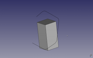
First experiment was to create a 50 X 50 X 100 cube and draw a DWire around it.
 This is rather amusing .. I was just doing this by eye and it looked liked I was drawing a Dwire to run along the edges of the Cube, but alas it was a delusion errrr..illusion.
So here’s some python code that I got from the macro recording.
# Macro Begin: /home/jonasthomas/FreecadMacros/tubeBendingTest2.FCMacro +++++++++++++++++++++++++++++++++++++++++++++++++

import FreeCAD
#Gui.activateWorkbench(“DraftWorkbench”)
#FreeCAD.DraftWorkingPlane.reset()
#FreeCADGui.Snapper.setGrid()
points=[FreeCAD.Vector(-14.6794960144,-38.9710840913,-16.3023618386),FreeCAD.Vector(15.2086099949,-28.9646975892,-35.2383949065),FreeCAD.Vector(35.6627437396,30.6707607136,-8.51311612836),FreeCAD.Vector(-12.855674845,67.2145578579,61.9107004988),FreeCAD.Vector(-53.5142064538,49.0614256623,84.25678738),FreeCAD.Vector(-72.0758478468,-1.99392771167,62.3064716498)]
Draft.makeWire(points,closed=False,face=False,support=None)
#Gui.activeDocument().activeView().viewTop()
#Gui.activeDocument().activeView().viewTop()
#Gui.activeDocument().activeView().viewTop()
FreeCAD.getDocument(“Unnamed”).getObject(“DWire”).FilletRadius = ‘1 mm’
FreeCAD.getDocument(“Unnamed”).getObject(“DWire”).FilletRadius = ‘2 mm’
FreeCAD.getDocument(“Unnamed”).getObject(“DWire”).FilletRadius = ‘3 mm’
FreeCAD.getDocument(“Unnamed”).getObject(“DWire”).FilletRadius = ‘4 mm’
So it looks like points is a list of freecad vectors which goes into Draft.makeWire. There seems to be some magic that’s occuring prior to the python commands being sent. It seems like there are some fake lines(for a lack of a better term) prior to the python scripts creating the object for real.
From Gui behavior it appears that Dwire can be appended.. So I found a little documentation on makeWire here
Description: Creates a DWire object from the given list of vectors or from the given Wire. If closed is True or if first and last points are identical, the wire is closed. If facemode is True (and wire is closed), the wire will appear filled. The current line width and color from the Draft toolbar will be used.
Returns: A new Draft DWire (not a Part Wire).
Ok…… So what’s the difference between a DWire and Part Wire??
A little more info here. http://www.freecadweb.org/wiki/index.php?title=Draft_Wire
Ok.. Experiment#2.. I want to try to record a macro where I create a Dwire, do something else and then try to append points to the Dwire.. Lets see what it looks like.
# Macro Begin: /home/jonasthomas/FreecadMacros/tubetestC.FCMacro +++++++++++++++++++++++++++++++++++++++++++++++++

import FreeCAD

import Part
#FreeCAD.DraftWorkingPlane.reset()
#FreeCADGui.Snapper.setGrid()
points=[FreeCAD.Vector(-2.21234130859,-0.494456797838,0.0),FreeCAD.Vector(-1.5398799181,-0.115844115615,0.0),FreeCAD.Vector(-0.935229718685,-0.890022337437,0.0),FreeCAD.Vector(-0.72049421072,-0.110193289816,0.0)]
Draft.makeWire(points,closed=False,face=False,support=None)
#Gui.activateWorkbench(“PartWorkbench”)
App.ActiveDocument.addObject(“Part::Box”,”Box”)
App.ActiveDocument.ActiveObject.Label = “Cube”
App.ActiveDocument.recompute()
#Gui.SendMsgToActiveView(“ViewFit”)
#Gui.ActiveDocument.setEdit(‘Box’,0)
#Gui.ActiveDocument.setEdit(‘DWire’,0)
#Gui.ActiveDocument.setEdit(‘Box’,0)
#Gui.SendMsgToActiveView(“ViewFit”)
#Gui.getDocument(“Unnamed”).getObject(“Box”).Visibility=False
#Gui.getDocument(“Unnamed”).getObject(“Box”).Visibility=True
#Gui.getDocument(“Unnamed”).getObject(“Box”).Visibility=False
#Gui.getDocument(“Unnamed”).getObject(“DWire”).Visibility=False
#Gui.getDocument(“Unnamed”).getObject(“DWire”).Visibility=True
#Gui.getDocument(“Unnamed”).getObject(“Box”).Visibility=True
#Gui.ActiveDocument.setEdit(‘DWire’,0)
#Gui.ActiveDocument.setEdit(‘DWire’,0)
#Gui.activeDocument().activeView().viewFront()
FreeCAD.getDocument(“Unnamed”).getObject(“DWire”).Closed = False
FreeCAD.getDocument(“Unnamed”).getObject(“DWire”).FilletRadius = ‘2 mm’
FreeCAD.getDocument(“Unnamed”).getObject(“DWire”).FilletRadius = ‘1 mm’
FreeCAD.getDocument(“Unnamed”).getObject(“DWire”).FilletRadius = ‘0 mm’
FreeCAD.getDocument(“Unnamed”).getObject(“DWire”).FilletRadius = ‘0.1 mm’
# Macro End: /home/jonasthomas/FreecadMacros/tubetestC.FCMacro +++++++++++++++++++++++++++++++++++++++++++++++++/
Ok… This is getting more curious.. Apparent the macro recorder is recording everything… The dwire can be appended… Ok.. Now the question is how to do that programatically…
It’s been a year or so since I’ve messed with this stuff… time to google myself 😉http://forum.freecadweb.org/viewtopic.php?f=10&t=3380&start=40#p26606
I think I need to poke around this code for a while. So it looks like draft.Makewire is defined here:
Basically:
def makeWire(pointslist,closed=False,placement=None,face=True,support=None): ”’makeWire(pointslist,[closed],[placement]): Creates a Wire object from the given list of vectors. If closed is True or first and last points are identical, the wire is closed. If face is true (and wire is closed), the wire will appear filled. Instead of a pointslist, you can also pass a Part Wire.”’ import DraftGeomUtils, Part if not isinstance(pointslist,list): e = pointslist.Wires[0].Edges pointslist = Part.Wire(DraftGeomUtils.sortEdges(e)) nlist = [] for v in pointslist.Vertexes: nlist.append(v.Point) if DraftGeomUtils.isReallyClosed(pointslist): closed = True pointslist = nlist if len(pointslist) == 0: print(“Invalid input points: “,pointslist) #print(pointslist) #print(closed) if placement: typecheck([(placement,FreeCAD.Placement)], “makeWire“) if len(pointslist) == 2: fname = “Line“ else: fname = “DWire“ obj = FreeCAD.ActiveDocument.addObject(“Part::Part2DObjectPython“,fname) _Wire(obj) obj.Points = pointslist obj.Closed = closed obj.Support = support #obj.MakeFace = face if placement: obj.Placement = placement if gui: _ViewProviderWire(obj.ViewObject) formatObject(obj) select(obj) FreeCAD.ActiveDocument.recompute() return obj
Ok..It looks like the wire magic occurs in _wire
which is define line 4078
So there is some interesting stuff going on with the fillet radius here which takes you to to filletwire
Ok… this is making my head ache. I think I have my trail of breadcrumbs to follow… What I want to do next if figure out how to append a point to an existing DWire object.
