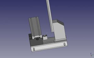
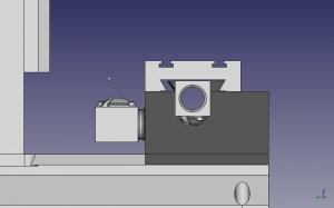
[Edit I was looking at my 7820827 ball nut and comparing it to the 8106-448-022 solid I downloaded.. It seems that the wall thickness is not uniform. The side with the return tubes appears thinner than the opposite side.]
My Mcmaster ball screws where made by Thomson and have a part number 7820827.
I was searching around for some 3d models and I found one on the Reid sight which match the part number, but unfortunately, something got hosed up in the registration so I couldn’t get the file.
I was looking at the Thomson site and I found the partnumber 8106-448-022 seems to be equivalent as far as it’s envelope. Looking at a Thomson catalog I downloaded seems the difference is in the major screw dia:
8106-448-022 (0.610)
7820827 ( 0.620)
 I did see one small difference. The 8106-448-022 shows a cross-hole hole in the thread and the part I have has a flat.
Placing the ball screws help alot. Currently I have the saddle height at 2.375. I was thinking that I could get by using the original base support so I was shrinking the saddle height. I have ~2.52 inchs of height on raw material available. The bolts that screw into the base column go in 1/2. I need to model that to see if I’m going to hit the “Y” axis lead screw.
 I think I’m going to move the x-axis Ball nut a bit also, since I might hit the tapered gib.
If I have clearance I might drop it down a bit also.
