I had some funky music going through my head when I wrote that title.
Ok.. Some I working my way to modeling my the x-axis ball screw shaft. One thought at the moment, is there’s going to be all kinds of purchased stuff, that is going to this assembly. I should be able to align up everything to the axis of rotation and then draw the shaft to this. So on this shaft assembly, the stuff that’s going to be aligned to the axis of rotation is going to be:
- The ball screw shaft itself
- The x-axis bore of the saddle
- Two bearings
- A nut.
- A washer
- The ballscrew nut
- A pulley
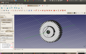
 Just for fun, I created a sketch in the x-y plane 0,0,0 and then loaded the step file of the SPD pulley I’m planning on using. It appears that the local origin of the object is centered in the bore (which you’d expect) and the axis of the pulley runs along the pulley. The zero point appears to coincide with the face of the pulley.
It seems like I should just be able to click on the local origin of the part and then click on the axis of a part and have it all magically align.. I done think FreeCAD can do that yet..
