Results of the calibration checks and next steps

I make a little how cylinder in free cad and printed it out and measured it.  Hear are the results

DRAWN IN FREECAD
MM INCH Measured Measurement method Comment
Hollow cylinder ID 11 0.4331 0.399 Gauge Pins Huh?
OD 17 0.6693 .669-.680 Digital Veneer
LENGTH 10 0.3937 .395 -.400 Digital Veneer
Pin OD 0.196 .208-.214

This is not what I expected… I deburred the ends of the bore with a chamfering tool and then inserted a gauge pin such that it had barely went on freely.

The gauge pin is much closer to 10 mm ( .3937) than it is to 11mm. At first I thought I misnamed the model, so I went back to check how I dimensioned it… R =5.5 mm
So then I overlayed the Stl over the sketch and it showed that it meshed.   This makes no sense to me at all.  I’m a full mm off on my bore but the od is ok.

I know that when I drew this out originally I used 11 R and 17 R on the radius, which I immediately killed the print and when back to my Freecad computer and fixed that uploaded the stl file  and then downloaded to my printer computer…   I overlayed the STL to the sketch and it matched…   I’m thinking I messed up somehow and I need to redo the freecad sketch pad the stl etc… and see what happens…. Although for the life of me, I don’t know how I did that…

Anyway… way too tired tonight to mess with this…   What I wanted to do was do a little research why my nozzle keeps scraping on my table in my first 3 layers and then causes a motor skip… But the sandman is here…

Just a quick update….  I did a quick search on the search terms… “correlation between layer height and nozzle gap reprap” http://forums.reprap.org/read.php?1,131648 

and this discussion thread popped up on the top of the list…. Die swell… Ok…. thats a new one on me….  I need to re-read that link over some morning java…  Why is it the more I learn the less I seem to know.? Machining in metal seems way more straightforward to me, as opposed to pooping plastic…

2013-07-28-151434

Posted in Uncategorized | Leave a comment

Using gauge blocks to check 3d printer calibration

So there have  been a couple of issues that have been bugging me in my last series of prints that I want to do a full 20 mm calibration cube.

One thing was some sizing issues on some model I downloaded from thingiverse.  Basically there where some pins that where coming out way thick for the gears they went into.

Also it seems like the center distance was a little short when the gears where pressed together with a little backlash.

Another issue I was having was when I did a manual z move to place a gauge block it seems like I was coming up short…

So… this is a calibration cube I decide to go all out and break out the gauge blocks..  When I had to build up blocks I usually just figured it out without any particular algorithm…   I ran across one here.   http://www.northerndtool.com/gage-bloc

2013-07-28-000148

The algorithm is pretty simple  basically calculate your size to 4 places… So… I need 20/25.4= .7874″ What you do is find a gauge block to zero out the .0004   so… .1004 and subtract, repeat with the .001 and then the .01

Soo
.7874
-.1004
———
.687         .687    .687
-.117         .127    .137
——–       ——-    ——
.57            .56       .55
.55
——
0
So you make sure the block are lean and they should stick together by themselves.

When I check them against my harbor freight verneer I get .787 to .788  Anyway… I to tired to read the OD mic tonight… So I’m just going to zero out the vernier to the Gauge block and see what the variations are.

measuring along the x-axis parallel .002 -.005 to the layer… Perpendicular to the layers (avoiding the bottom smooshed lather .012-.150  (I think I might be picking up an out of square condition.

Y-axis. .003-.007  (parallel to layer .005-.007 perpendicularly measured across the vernieer.

Z-axis .000-.006
Actually I’m quite pleased with this… I think the table sinks a bit.. I’m thinking if I correct that I could get something a little tigher
I think I might be see some out square with my z-axis.. which is the weak point in this iteration the rockbot..   I’m thinking one more test in the morning I’m going to print out a hollow cylinder in a range that fits my gauge pins…  I’m going to draw it in freecad so It’s a known size and then run a test…

11 mm bore should work…

Hmm. While I’m at it I have a left over base from that thingiverse part… It takes a .196 pin… I’m going to draw a .196 pin in freecad and see where that prints out at. But that’s for another day.

2013-07-28-004413

Posted in Uncategorized | Leave a comment

Preliminaries on doing a fine height adjustment on the z-axis of a 3d printer.

The thingiverse paper crimper http://www.thingiverse.com/thing:17634  was some what disappointing to me… I was experiencing some pretty signficant size variation between the pins and what they fit into also it seems that my z-axis optical endstop is drifting the the position of my table is being moved when I try remove a stuck part from the table…  Part sticking has not been an issue other that parts probably sticking too well.  Reading through the thingiverse comments it sounds like there’s minimal sizing issues.  I’m thinking that I really need to print a full calibration cube to see what I got going on.  I loaded up the pins an a gear in freecad and assembled them… Seems like clearance is ok.. Is it leaning towards a calibration issue..

Anyway the subject of this post was fine height adjustment of a z-axis.  The problem is that  on my printer it’s a pain to do fine Z-height adjustments on the optical endstop.  I want to be able to easily raise or lower in .001 increments.
Z-axis Optical Endstop

The plan is to  create another split adapter and place it below the one shown in the picture and drill and tape both the upper an lower with concentric threas..  The plan is to put a double ended thread rod assembly each with slightly different pitch on either end. The bottom adapter would fixed to the rod and the upper would allowed to float during height adjustment mode (fixed otherwise)..   Think of it this way… both split adapters had the same pitch threaded hole and I turned in a threaded rod, there would be no relative motion between the two adapters.

    1/4-20 1/4-28 6mm X1 6mm X1.5 32TPI
    0.05 0.0357142857 0.0393700787 0.0590551181 0.03125
1/4-20 0.05 0.0000 -0.0143 -0.0106 0.0091 -0.0188
1/4-28 0.0357142857 0.0143 0.0000 0.0037 0.0233 -0.0045
6mm X1 0.0393700787 0.0106 -0.0037 0.0000 0.0197 -0.0081
6mm X1.5 0.0590551181 -0.0091 -0.0233 -0.0197 0.0000 -0.0278
32TPI 0.03125 0.0188 0.0045 0.0081 0.0278 0.0000

This table was created to see what the pitches for common threads an what the differential would be subtracting them..(I was really tired when I did this, so if someone is going to use this please double check the numbers)  The smallest move I could get was about .0037 between a M6 X1 thread and 1/4-28
I think I like 1/4-20 an 6mm-1 I  combination for a couple of reasons:

  • should get a differential movement of about .0106 per rev which is close enough to put a 0 to 9  inch dial on.
  • I have both thread rods/taps in stock
  • I shouldn’t run into the upper bearing block while making adjustment

So thats it for about now.

Posted in Uncategorized | Leave a comment

Even more 3d printer stuff.

So.. One of the things I’m observing is that first layer seems to be some what critical… Too thick and too close it causes the nozzle to scrap on subsequent layers and I got a motor skip…
Too far, you get squiggly lines and suspect that adhesion isn’t too good.  On my motor mount prints, I left them over night on the print table but I was getting some crazy adhesion… That’s the one where I had a lot of scraping…   I had double faced tape holding my glass table down to the y-axis support.   I wound up pulling that apart try to get it off the table…

So I’m heading past my sister these weekend and I told her that I  print her a paper crimper. http://www.thingiverse.com/thing:17634   I thought I had my height calibration dialed in from the night before and I wound up scraping..  So one of two things I think happened.  Things moved a bit from when I tried getting my last print or I’m getting some drift on my z-axis optical endstop..
So I readjusted to one paper thickness and tried a few prints..  I had that scrap issue on the first layers and a skip..  When I went to .15 on first layer thickness everything seemed to work ok..

Hmm either calibration block next (same color.. or gears… )  Running out of time… I guess it’s time to switch over to green.  It does seem like 210 is a little hot for my green… I’m back down to 200..

Hmm… Out of time… Results disappointing.   Had to make some metal pins..

2013-07-26-114936 2013-07-26-125814 2013-07-26-143014

Posted in Uncategorized | 1 Comment

Starting to get into some fine tuning on the 3D printer…

This is starting to get interesting… My PTFE liner mod is still holding up… Continous printing so far…

I’m thinking I should make a filament cleaner…  repercussions of the last  clog really screwed me up..

I was looking at filament cleaners on thingiverse and I stumbled on the link for the MK-7 extruder…. What’s curious is the glowing reviews…

Seeing the the qu-bd was it’s clone. seems like the MK-7 should have had the same issue… http://www.thingiverse.com/thing:11734  go figure..

Anyway… Here’s a link for filament clearners  http://www.thingiverse.com/search/basic/page:1?q=filament%20cleaner .   There’s a bunch of options I need to perculate on this a bit…

Tonights print was spool bearing adapters..   For some reason, this print has been problematic for me…   This go around,  I had the table well aligned and the tip about a sheet of paper way from the table (Guestimating .004)   Since I have alignment close to perfect, I had the first layer print out sort of mushed…  This compounded for the first couple of layers  and I had scraping which resulted in a slight skip.. which worked itself out. OTH… That was probably the best adhesion I’ve ever done.slightSkip

I’m looking at the Slicer settings and I should have trimmed down the thickness of the first layer.   This is something that I need to research a bit more.

Also, when I tried to raise up .120″ by going  G1 Z3.048 I fell signficantly short..  (I could swear that I had that done correctly…) I’m going to need to read up on the sprinter G-code commands

http://reprap.org/wiki/G-code#Unbuffered_G_command

; generated by Slic3r 0.9.11-dev on 2013-07-25 at 14:05:06

; layer_height = .3
; perimeters = 3
; top_solid_layers = 3
; bottom_solid_layers = 3
; fill_density = .2
; perimeter_speed = 30
; infill_speed = 60
; travel_speed = 90
; nozzle_diameter = .35
; filament_diameter = 1.74
; extrusion_multiplier = 1
; perimeters extrusion width = 0.35mm
; infill extrusion width = 0.37mm
; solid infill extrusion width = 0.37mm
; top infill extrusion width = 0.37mm
; first layer extrusion width = 0.60mm

G21 ; set units to millimeters
M107
M104 S215 ; set temperature
G28 ; home all axes
G1 Z5 F5000 ; lift nozzle
M109 S215 ; wait for temperature to be reached
G90 ; use absolute coordinates
G92 E0
M82 ; use absolute distances for extrusion
G1 F1800.000 E-1.00000
G92 E0
G1 Z0.300 F5400.000
G1 X64.964 Y36.002

SlicerSettingsforBrgadapter

Next steps:

  • Review proper settings for first layer…  (Review http://reprap.org/wiki/Triffid_Hunter%27s_Calibration_Guide) for guidence and make adjustment
  • Put .003 shim under the low side of the y-axis to see if we can improve parallelism..
  • Need to figure why a manual move doesnt seem to be working.  Probably should run a 20mm cube to see if it’s really 20mm height.   I need to verify that  my firmware settings are correct (hopefully) or fix them.
  • Assuming settings are correct, I might need to increase E just a tiny bit.2013-07-26-024118
Posted in Uncategorized | Leave a comment

Focusing on calibrating the z-axis motor height for the x-axis.

Previously, I had done a quick recalibration and set parallelism using  a set of feeler gauges between the nozzle and blue tape.  When I had printed out the halves of the Despicable me http://www.thingiverse.com/thing:34204, I discovered quite  by chance that my x-axis was not has parallel with the table as I thought.  The character was printing in two seperate halves..  On the first 3 layers I noticed that the half on the center of the table printed nicely, while the right side (from my perspective) had squiggly lines.   I’m thinking that the z-height distance between the tip and the table was slightly longer their.

At this point, I wanted to see if could get a feel for what the heck was going on.   Since at this point, I’m not interested in setting height,  I stripped off the blue table to work off the datum.

The feeler gauges should of worked, perhaps I was in too much of a hurry, or the blue table caused some issues.   I was thinking about using a dial indicator, but it would be awkward.With the gauge blocks I can go down to .0001 height differences if I need to.

Gauge Blocks

Gauge Blocks

guagingDistanceJust to get started, I homed the z-axis and I had a gap in excess of  .030″ with the feeler gauge.   I want to zero out to a .120 gauge block which is in the middle of my .001 range blocks.
So… I jogged the z to where the .120 when smoothly and the .121 had the slightest resistance.   I then disconnected the z-axis motors from Ramps and jogged over the x to the other side.
Now this was surprising to me.. The right side (from my perspective) the side that produced the squigly lines was less than a .120 gauge block. I was anticipating it was going to be more.
So… time for a more exact measurement. Wow… .102 went. .103 had resistance…   Yikes… .018″ that’s alot…

So I went back and forth a few times on the x-ax

is to get everything set to .120 go .121 no go.
So… Once the one side was zero’d out. I had a bit of a scare when I reconnected the z-axis motors…  Nothing happened..   I thought for a amount that I had either fried a polulo or worse messed something up on the ramps… I  was in a bit of a panic, until I powered everything done computer, arduino and brought it back up… It seemed to worked fine… In hind site, I shouldn’t be disconnecting/reconnecting motor with the power on… dumb dumb..

So with the Z-height trammed in on one side of the table, I tested against the opposite side.  I seems that I have a downward slop along the y-axis of about .003 left side .004  right side.   I think that’s pretty darn good actually (sounds of me slapping myself on the back)…  I took great pains to make sure I machined my components accurately and precisely.    When I put together the table, I just tried using double side tape with no table adjustment features…   I suppose at some point, If I want to correct for .003-.004″ I could do that, but for now… I think that probably meets most of the repraps out there.

Conclusions and lessons learned: My z-height needed adjustment.   Gauge blocks on glass are really nice to use for adjusting height.  You can easily set height to w/n +-.0005

Things for the future. 

Setting my z-height is sort of hit or miss. Currently I don’t have direct fine adjustment for the z-height.   What I was doing was either doing it by watching the light strength on the sensor or using height blocks in the gap between the split bushing and the z-axis bearing block.  Seems like there could be some improvement there.

Z-axis Optical Endstop

Quick addendum.  I wanted to do a quick height calibration..   I want .006 on the high side of the table… So I want to zero out and offest .120 and have it take a .126 gauge block. on blue tap..120 = 3.048 mm… Hmm Something not correlatting…  I wonder if something is messed up with my z axis step settings…  Uggg. Something for another day.

Posted in Uncategorized | Leave a comment

Re-calibrating the printer.

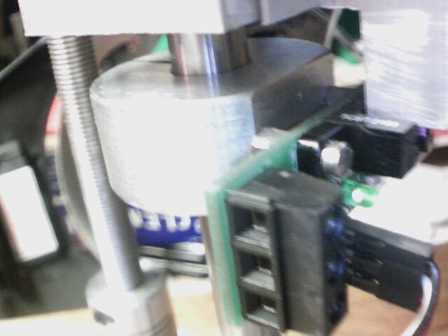
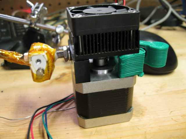
I basically slapped my qu-bd extruder back to together after some pretty substantial mods, and using a new material ( translucent blue) and tried printing with original settings.. And things didn’t work… Go figure….. I’ve got a few variables to deal with..
What was happening was that the nozzle was scrapping on the top of the print, with a severity that it was causing the motors to loose steps… and print quality was too good either…

So time to reduce some of the variables.

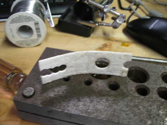
Excesssive Play in Z-Axis:
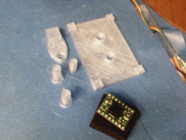
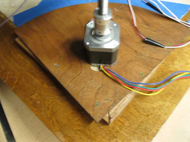
My printer is a custom built.  I made some plywood plates to keep my z-axis motors from rotating and I never secured them.  I assumed when I was cutting these plates was that the center line of the leadscrew and the z-axis line, intersected the diagonal of my marble plate… A bit of an oversight on my part… doh…. So things are a little off… Perfectly functional… but messes with the whole feng shui aspect of things…. Actually I’m not sure how feng shui’ish a home made 3d printer can be.. but there you go…..  If I get around to a MKII rockbot, I think I’m going to redo this entire arrangement.  I had been virtually modeling everything in freecad but at this point of the project, I was going freestyle an making stuff on the fly without any drawings.  Some basically I screwed the plywood to some oak strips which where located against the edge of the marble plate and now the thing is secure:

Axis not in line with the diagonal revealed.

Axis not in line with the diagonal revealed.

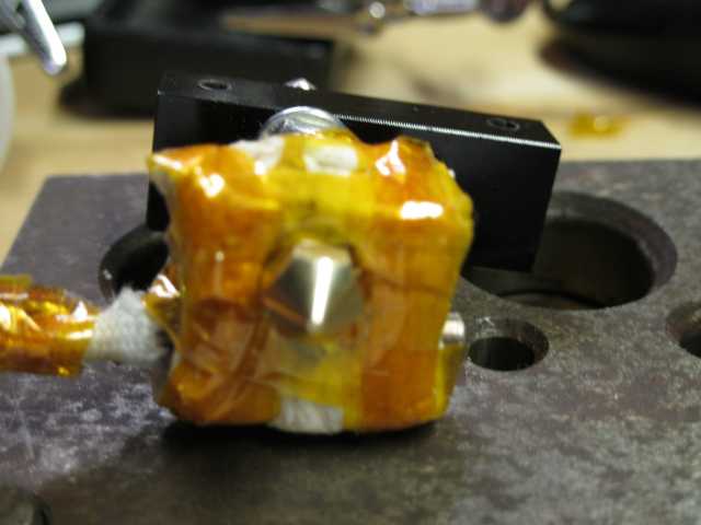
X-Axis Rail not Parallel to table:

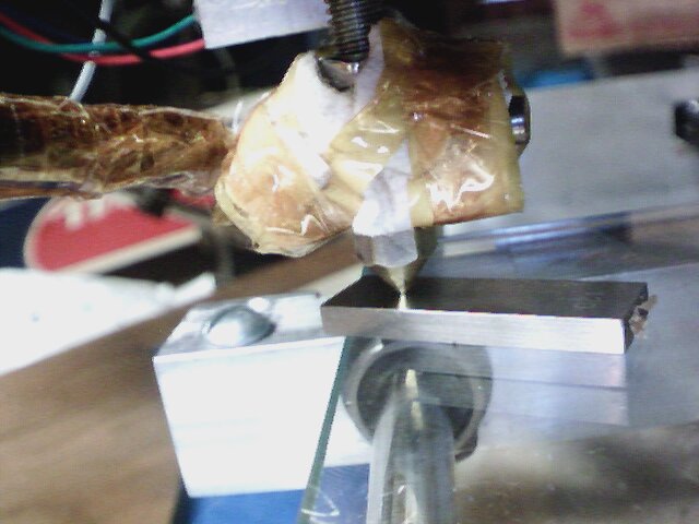
One thing I noticed is that lost parallelism between the x-axis carriage and the table… I checked that using a shim between the nozzle and the table and adjusted the height by turning the z-axis motors individually. (They where significantly off)

Increased temperature (Unknown if from rebuild or Matl):

With the clear Pla, it seems like things extrude better around pla… but…. I have a new thermistor mounted slightly differently then last time so it could be that….  But for know for this material, 210C is where I’m at this I get the other unknowns stabilized…
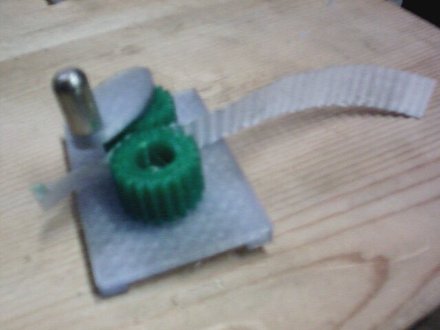
E Adjustment:

Things seem to have improved with the above changes… But I ran a calibration block and I don’t like the results I’m getting on the rapid fills… Part of the rework was I through a different hob wheel on,  I’m wondering if the pitch diameter changed  a tiny bit and the extruder is putting out slight more per step…  Soo… I need to refer back to my calibration notes.  (What a yucky post… http://www.metalshaperman.com/?p=1565   (The wife just called saying about how she mentioned to her co-workers that they want to see samples… )  which refers me to hunters guide.. http://reprap.org/wiki/Triffid_Hunter%27s_Calibration_GuidePuttingitOnALilThick

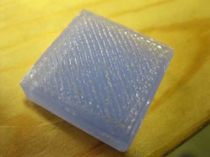
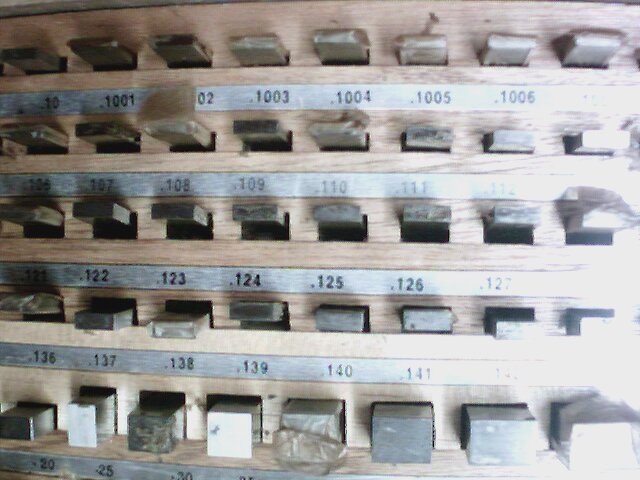
Soo….  I’m going to measure and mark off and extrude 100 mm and see the difference between theory and actual…  The results 100 mm theory equals about 108mm actual…   Wow… theory, observation measurement jive…. I’m feeling lucky…
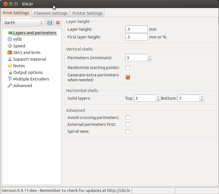
My current settings are float axis_steps_per_unit[] = {87.489, 87.489, 3023.622,108};

I believe I need to adjust the 108… The formula is:
calculate new_e_steps = e_steps * 100mm / measured_distance
108*100/108 = 100 (Now that’s easy math…) I’m feeling luck plus running out of time before work, so I’m just going to flash the new value into the firmware and start printing…

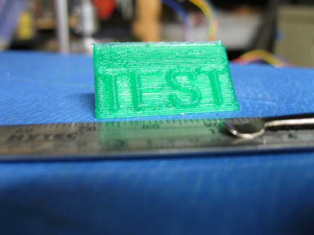
Running a test print:
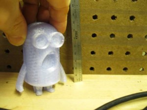
So.. I’m seeing some very interesting things in my test print…   I’m using this http://www.thingiverse.com/thing:34204 and I’m printing both halfs at the same time.   On the first couple of layers one half is printing beautifully and the other half started printing with squigly lines… I’m thinking I still have some paralleism issues… Hopefully things will even out on the next couple of layers.  Also, I think I’m going to need to start playing around with retraction…. (which is something I haven’t really worried about yet… It seems like things get a bit thicker on the ends than they should be….
So on the third solid infil layer things seem to have evened out a bit…  I wonder if someone has made a fixture for testing parallellism…. I seems like this would be easy enough to print out… Hmmmmm.   I could use that lettering stuff I’ve been messing around in freecad..DespicalblemeComponents DespicableMeAssembled
Conclusions:
So far I got about 5 hours (according to Repartier pre-calculated time) of printing in with the custom Modification that I did… I’ve had a bunch of bad prints but I think that was more calibration issues than anything.  I fixed up the play on my z-axis.  Aligned the x-axis parallelism, and tuned the mass flow.

Next Steps:

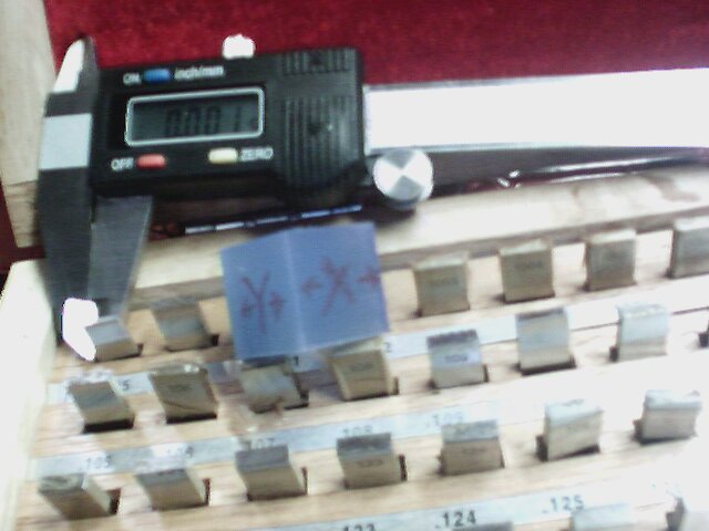
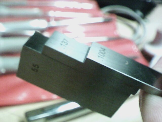
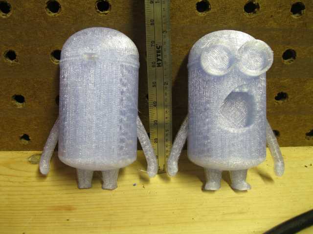
It was a bit of serendipity was that I printed the despicable me’s.  Basically i was talking to the wife at work and she told me one of her co-workers would love one.   I provided me an indication that I’m having some type of alignment issue still.  In  first three layers I had a major difference in print quality, which I’m attributing to my feeler gauge aligment not being accurate enough…  I think  I’m going to break out the dial indicators and see if I can do a more quantitative vs qualitative analysis as to why I’m having these issues.

After that probably print some green to see if it runs  at a cooler temperature.

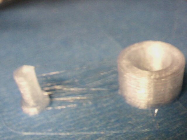
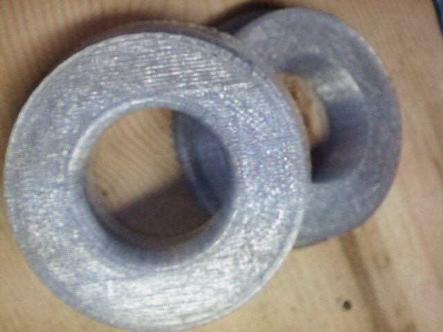
At that point, hopefully I can run some hours to see how the mod holds up… (I probably would get a wiper for the filament to reduce clogging issues.)  I’m feeling pretty good about it… I’m planning on popping out another PTFE stub/nut combo and another custom tube so he could give it a try on his qu-bd extruder.


Posted in Uncategorized | Leave a comment

Getting backinto the 3d printing swing of things..

I ordered a spool of translucent blue pla from ultimachine and started off printing it with my reworked head.

Also, I keeping a spreadsheet to keep track of how much printing time I’m getting on my modded head…  I’m running low on my green pla and I want to preserve it for my yoda heads and minecraft creepers 😉

So… I think I’m working with too many unknown variables at the moment…  That is, a rebuilt extruder head and different material..  At this point, it seems like I had to set my flow rate to 94 percent of my green and it seems, like running at 205 is better than the default 200…  But…. I won’t know if that’s the material on the head until I put some green back in.

At the default settings it seems like I’m getting some goobers (hows that for a technical description)…  I think the material isn’t printing out flat and when the nozzle passes over it it’s rubbing which winds up aggrevating the situation and getting worse…  At least its my working “A” theory at the moment.   Couple of other thoughts as to what might be happening, but I’m just tuning down the flow rate in Repetier for the moment an upping the temperature to see how that works out..

Prior to my jam, I was getting used to just printing… I think I’m going to got back through the calibration procedure.. It seems like I’m putting more material through the extrude than before..

Anyway…I’ve been staying up way too late.. Time to take out the garbage and its off to be..

Posted in Uncategorized | Leave a comment

Playing around with freeCAD, 3d printers an gears.

Ok.. I want to use my 3d printer to make a small rotary table for Halloween pumpkin.  I’m thinking of printing out something with bearings races similar to an angular contact bearing with an integrated ring gear.   I have a couple pinions I could find a use for those raptor gears that I replaced.   I rolled them against some 48 pitch gears in my surplus gear box and they it seemed to roll pretty size..   At least I thought they where 48 pitch… I guess I should do a lil calculating…
There’s a nice little sight with a bunch of formula for spur gears. http://www.cage-gear.com/spur_gear_calculations.htm   So to calculate DP Pd = (N+2) / OD =   (20+2)/ .455 = 48.3 ~ 48

Let me try that the other way… OD = (N+2)/22  22/48 = .458  Ok… Seems like that’s right… So.  Ok.. So since freeCAD only does metric (big sigh) we need to bounce around systems.   So I’m thinking I want a 48 pitch ring gear some where around 100mm 3.937″   So that means I need about 3.937 X 48 ~ 188.97.    Just for fun lets go with 200 teeth.

So.. I need to fill in the freecad input screen.  According   http://www.engineersedge.com/gear_pitch_chart.htm

48 Dp => goes to a circular pitch of 1.661 MM.
Other Particulars Addenum .0208″
Dedendum .0270″
WD .0478
Circular Pitch .0654

So.. I want to figure how to get that into the gear.py input form which from the repository looks like this(with its fault values:)

IssuesTryingtoPutHoleingear DefaultvaluesofGear.py

I need to look at  y, c,&j  at bit The problem that I’m having at the moment.  Is that if I use the code that’s in the repository and try some subtraction everything goes blank.  Not sure whats going on here with that..
(Everything comes to a screeching halt)… I had gotten an alternate script but that seems to take a lot of time.
Well this isn’t going to get solved tonight.

[Edit , wanted to fire up the printer and just print out a 200 tooth 48 dp gear…]
When I tried adjusting the first 2 parameters an this is what I got..  (Looks pretty but not exactly what I was looking for…
Let me drop the number of teeth to 59 and see what happens.
firstAttemptat48Dp200Teeth

Ok.. This is rather amusing… with 59 teeth generates a gear with a few missing teeth.  Ok… Lets try 40 and see if we get something.

seemtoBeMissingafewTeeth

40TeethSeemstoGenerate

Freecad Export to Stl... Something looking a bit weird
Freecad Export to Stl… Something looking a bit weird
Posted in Uncategorized | Leave a comment

Back in business.

Well repairs are complete…. Warp engine is back on line…  (Hm… Was watching some trek with the kid tonight..)

On my insulation around the heater I wanted to make sure I had clearance for a socket head.  When I need to remove the Nozzle (which will happen sooner or later I didn’t want to get insulation particles all over the place.  Also, I might want to do the layout for the insulation before I assemble..  I probably could have avoided the slot.
I’m curious how my mods perform. I’m keeping a log of print times to see how it does. I estimated 20-30 hours last go around, but thats just swag.

Anyway.. A few pictures..    I had a couple of people ask me what the extruder looks like.. Theres a pick as well as the mount.

Printer Head on my punch die block

OneWaytwoSpotahole Printer Head on my punch die block

InsulationPunchoutoutEverythingTapedUpMountForMotorAssembledExtruder
FirstPrintWithRebuiltPrinterHead

Posted in Uncategorized | Leave a comment